UHV Transformer Production: Slow, Precise, Essential

1. Overview
Ultra-high-voltage (UHV) transformers are core equipment in modern power systems. Understanding their voltage ratings, complex structure, precision manufacturing processes, and critical production techniques reveals why they represent the pinnacle of a nation’s power equipment manufacturing capability.
Voltage Level Definition
The term "ultra-high-voltage transformer" typically refers to transformers used in AC transmission lines rated at 1,000 kV or higher, or DC transmission lines rated at ±800 kV or higher.
1.1 Technical Background
The development of such high-voltage transformers is driven by national economic and power sector growth, aiming to enable long-distance, high-capacity, and low-loss power transmission. For example, as early as 2010, China independently developed a 1,000 kV / 1,000 MVA UHV transformer.
1.2 UHV in DC Transmission
UHV technology is equally critical in HVDC (high-voltage direct current) transmission. For instance, the ±1,100 kV UHV DC converter transformer is one of the key products under China’s “Made in China 2025” and “Belt and Road Initiative” strategies, with its technology now recognized as world-leading.
2. Main Components
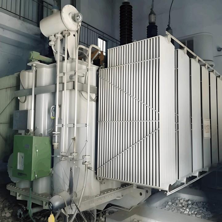
UHV transformers feature highly complex and precise structures. Taking a typical oil-immersed UHV transformer as an example, it primarily consists of the following components:
| Component | Functions and Features |
| Iron Core | It is made by laminating high-quality silicon steel sheets to form the main magnetic circuit. UHV transformers may adopt innovative structures such as six-module segmented core to reduce loss and facilitate transportation. |
| Windings | Including high-voltage windings and low-voltage windings. Generally, the low-voltage winding is wound on the inner layer, and the high-voltage winding is wound on the outer layer. It is the core component for the transformer to complete voltage transformation. |
| Insulation System | Including winding insulation, interlayer insulation and transformer oil. UHV transformers will adopt multi-layer molded corner ring insulation structure, compact tank wall barrier insulation structure, etc., to ensure sufficient insulation margin. |
| Oil Tank and Transformer Oil | The oil tank accommodates the iron core, windings and transformer oil; transformer oil plays the role of insulation and cooling. |
| Voltage Regulation Device | UHV transformers usually adopt neutral point on-load tap-changer for voltage regulation, and may adopt independent external voltage regulation mode, that is, the transformer main body and the voltage regulation compensation transformer tank are arranged separately. |
| Cooling System | It dissipates the heat generated during operation. UHV transformers may adopt advanced designs such as multi-channel body heat dissipation structure and new iron core clamp oil passage structure to optimize heat dissipation. |
| Protection Devices and Bushings | Including conservator, gas relay, moisture absorber, safety airway, etc. High-voltage and low-voltage insulating bushings realize the connection between internal leads and external lines, and ensure insulation to the tank. UHV bushings have complex designs, for example, multi-layer insulation cylinders and support stay structures will be adopted to ensure uniform electric field. |
3. Manufacturing Processes and Key Technologies
The manufacturing of ultra-high-voltage (UHV) transformers is a systematic engineering process that spans from raw materials to finished products. The following outlines its main production stages:
| Stage | Core Content |
| Design and Material Selection | Conduct electromagnetic, insulation, structural design based on electrical parameters, and select high-quality silicon steel sheets, oxygen-free copper wires, high-performance insulating materials, etc. |
| Iron Core Manufacturing | Including shearing, stacking and clamping of silicon steel sheets. Dimensional accuracy and stacking quality directly affect magnetic circuit performance and no-load loss. |
| Winding Production | Wind coils on special winding machines according to design parameters and perform insulation treatment (such as wrapping insulation paper). The number of turns must be accurate, the arrangement tight, and the insulation reliable. |
| Insulation Treatment and Drying | Windings and the transformer body need to undergo vacuum varnishing and drying to improve insulation performance. For UHV products, high-power gas-phase drying devices may be used during on-site assembly to ensure the moisture content of insulating materials ≤ 0.4%. |
| Oil Tank and Component Manufacturing | Manufacture transformer oil tanks and metal structural components such as clamps and shields. |
| Final Assembly | Integrally assemble the dried iron core, windings, leads, etc. in the oil tank, including arranging and fixing the leads, and installing accessories such as bushings and cooling devices. |
| Inspection and Testing | A series of strict tests are required before delivery, such as insulation withstand voltage test, no-load/load loss test, partial discharge measurement, temperature rise experiment, etc. |
The following key processes are critical to the performance and service life of ultra-high-voltage (UHV) transformers and require special attention:
3.1 Electromagnetic Design and Stray Flux Control
3.1.1 Importance
UHV transformers have very high capacities (e.g., up to 500 MVA per limb), making stray flux a more pronounced issue. Excessive stray flux can cause localized overheating and additional losses, jeopardizing safe operation.
3.1.2 Key Considerations
Advanced electromagnetic simulation techniques must be employed. Measures such as innovative yoke magnetic shielding and “L-shaped” copper shielding at tank joints are used to effectively reduce eddy current losses in structural components—by up to 25%.
3.2 Insulation Structure Design and Processing
3.2.1 Importance
The insulation system is the lifeline for reliable UHV transformer operation, as it must withstand extremely high operating voltages and potential overvoltages.
3.2.2 Key Considerations
Designs such as multi-layer molded angle-ring insulation structures are adopted to ensure uniform electric field distribution and sufficient insulation margin at coil ends and lead exits. Vacuum impregnation and drying processes must be strictly controlled—for example, using high-capacity on-site vapor-phase drying equipment to ensure thorough drying of insulation materials, achieving moisture content ≤ 0.4%. This is crucial to prevent partial discharge and insulation breakdown.
3.3 On-Site Assembly Process
3.3.1 Importance
In regions with challenging transportation conditions—such as high-altitude or mountainous areas—UHV transformers must be assembled on-site. This involves disassembly, transport, protection, and reassembly of thousands of components, making its design and process complexity far exceed that of conventional transformers.
3.3.2 Key Considerations
Modular structural designs are essential—for instance, segmented-core frames and detachable connection structures. On-site assembly tolerances must reach millimeter-level precision (e.g., coil-to-core center alignment deviation < 3 mm). A rigorous process for tolerance control, moisture prevention, and cleanliness protection is required to ensure post-assembly performance.
3.4 Winding Fabrication and Quality Control
3.4.1 Importance
Winding quality directly determines the transformer’s electrical performance, mechanical strength, and short-circuit withstand capability.
3.4.2 Key Considerations
Automated winding equipment must be used to achieve precise tension control and layer alignment. After winding, power-frequency withstand voltage and DC resistance tests are conducted to eliminate risks such as inter-turn short circuits.
3.5 Factory Acceptance Tests and Partial Discharge Measurement
3.5.1 Importance
These tests serve as the final quality checkpoint before delivery, identifying potential defects in design or manufacturing.
3.5.2 Key Considerations
Beyond standard tests, partial discharge (PD) measurement is especially critical. PD testing is highly sensitive to minute insulation flaws and serves as a key indicator of the internal insulation condition.
3.6 Coil Winding for UHV Transformers
3.6.1
| Stage | Role and Value of Manual Operation | Role of Mechanical/Technical Assistance |
| Core Winding Process | Dominant. Craftsmen rely on hand feel, eyesight and experience to precisely control thousands of details such as wire position, tightness, and placement of insulating parts. | Auxiliary. Provide a stable winding platform and basic power, but cannot replace the final fine adjustment. |
| Precision Control | Core guarantee. Top craftsmen can control the tolerance between two layers of wires within 1mm (industry standard is 2mm) to ensure optimal electrical performance. | Provide measuring tools (such as rulers), but the realization of precision depends on craftsmen's immediate judgment and fine-tuning. |
| Special Processes (e.g., Welding) | Irreplaceable. Facing hundreds of types of wires and thousands of welding points, craftsmen need to accurately control temperature, distance and time, such as high-frequency welding process. | Provide welding equipment, but parameter control and operation fully rely on craftsmen's skills. |
| Future Development Direction | The "tacit knowledge" of experienced craftsmen is still the core. | Intelligentization and digitalization. Convert the experience of excellent craftsmen into data for quality traceability and environmental monitoring, accumulating knowledge for future intelligence. |
3.6.2 Reasons Why Coil Winding Cannot Be Fully Automated
There are three main reasons why manual craftsmanship remains irreplaceable in UHV transformer coil winding:
3.6.2.1 Extreme Precision Requirements
UHV transformer coils are typically wound from thousands of meters of conductor, forming several thousand turns, with a final weight reaching 20–30 metric tons. Throughout the winding process, every tap of the mallet, placement of each insulating spacer, and wrapping of each layer of insulation paper must be executed with absolute precision—any deviation is unacceptable. This level of real-time judgment and micro-adjustment exceeds the current capabilities of machines, whose “hands” and “eyes” still cannot match the dexterity and intuition of master craftsmen.
3.6.2.2 Structural Complexity and Adaptability
UHV transformers come in a wide variety of designs with highly complex and variable structures. For example, in ±1,100 kV converter transformers, hundreds or even thousands of solder joints may be required to connect different types of conductors. Operators must adjust techniques on the fly based on minute differences in wire materials—akin to “connecting capillaries.” This non-standardized, highly adaptive decision-making and execution is precisely where manual skill excels.
3.6.2.3 Uncompromising Pursuit of Quality
A single coil involves tens of thousands of critical details. The slightest oversight—such as omitting one layer of insulation paper—can lead to insulation breakdown, resulting in rework costs of hundreds of thousands or even millions of RMB, and potentially jeopardizing the safety of the entire power grid. Given this extreme quality risk, relying on highly responsible and exceptionally skilled artisans remains the most dependable approach.
4. Production Capacity
In the UHV transformer industry, annual output is typically measured in total capacity (in kVA), not by unit count, because individual transformer ratings vary dramatically—from a few hundred MVA to over 1,000 MVA per unit.
4.1 Practical Capacity and Strategic Balance
Given the time-intensive nature of manual winding, how does the industry meet demand?
4.1.1 Reliability Over Speed
UHV transformers are often called the “heart” of the power grid, where reliability is paramount. For instance, Master Craftsman Zhang Guoyun has participated in winding over 10,000 coils over 25 years, with a total conductor length exceeding 40,000 kilometers. His hand-wound coils consistently achieve inter-layer conductor tolerances within 1 mm—half the industry standard of 2 mm. This exceptional precision, which machines cannot yet stably replicate, directly determines transformer performance and service life.
4.1.2 How Capacity Is Measured
These high-end assets are produced on a strictly “order-driven” basis, not for inventory—similar to building aircraft carriers or EUV lithography machines. Capacity is thus defined by how many qualified units a factory can successfully deliver in a year.
4.1.3 Strategies to Improve Overall Efficiency
To enhance efficiency without compromising quality, manufacturers invest heavily in cultivating large teams of highly skilled technicians. For example, “Master Craftsmen Innovation Studios” have trained over 2,000 employees in advanced winding techniques. Additionally, production planning and workflow management are optimized to ensure seamless coordination between core winding operations and supporting processes before and after.
| Content | Data/Scale | Key Information |
| Capacity of Industry Leader | TBEA has an annual capacity of about 495 million kVA | Represents the top domestic manufacturing scale. |
| Total Domestic Capacity | In 2023, China's UHV transformer capacity was about 50 million kVA (0.5 billion kVA), and it is expected to reach 60 million kVA (0.6 billion kVA) in 2025 | Reflects the overall capacity level of UHV transformers nationwide. |
| Manufacturing Cycle | The manufacturing cycle of UHV transformers is extremely long, usually taking 18 to 36 months | This is the most critical factor limiting annual output. |
4.2 Why Annual Output Is Limited
The annual production volume of ultra-high-voltage (UHV) transformers cannot be measured in “tens of thousands” like ordinary commodities, primarily due to their exceptionally complex manufacturing processes and extremely long production cycles.
4.2.1 Technically Complex and Time-Intensive
Often referred to as the “heart” of the power grid, UHV transformers are subject to extraordinarily stringent standards in design, materials, manufacturing, and testing. The entire process—from raw material procurement and precision fabrication of core components (such as windings and cores) to final assembly and months-long rigorous testing—takes a very long time to complete.
4.2.2 Capacity Allocated to a Few Mega Projects
Globally, only a handful of companies possess the capability to manufacture UHV transformers rated at ±800 kV or higher (e.g., TBEA, XD Group, Siemens, ABB). National UHV projects are approved and constructed in phases, with transformer quantities carefully planned in advance for each major project. For instance, a single UHV DC transmission project may require dozens of converter transformers. Consequently, the massive production capacity of leading manufacturers—such as TBEA’s nearly 500 million kVA—is dedicated to fulfilling specific large-scale project orders rather than producing inventory for speculative sale.
4.3 Industry Context and Global Demand
4.3.1 Strong Domestic Growth
China’s UHV grid construction is currently in a period of rapid expansion. According to national planning, during the 14th Five-Year Plan period (2021–2025), State Grid has scheduled 38 new UHV lines—comprising 24 AC and 14 DC projects—significantly expanding beyond the scale of the 13th Five-Year Plan. This provides a stable and growing domestic market for UHV transformers.
4.3.2 Surging Global Demand with China as a Key Supplier
Globally, the power industry is facing a severe shortage of transformers. Delivery lead times for standard transformers have stretched beyond two years, and for large power transformers, they now reach three to four years. Against this backdrop, China has emerged as a critical global supplier, thanks to its complete industrial chain, high production efficiency (e.g., while it takes foreign manufacturers about 18 months to build one UHV transformer, leading Chinese firms can complete it in approximately three months), and cost competitiveness. Transformer exports from China have surged—reaching RMB 29.711 billion in the first eight months of 2025 alone, an increase of over 50% year-on-year—demonstrating that China’s production capacity is actively meeting rising international demand.
4. Conclusion
As the “power heart” that transmits electricity across mountains and valleys, the UHV transformer embodies the highest levels of engineering sophistication—from design and materials to every single manufacturing step. It is precisely these rigorous processes and breakthroughs in critical technologies that underpin today’s modern, efficient, and highly reliable UHV power grid.