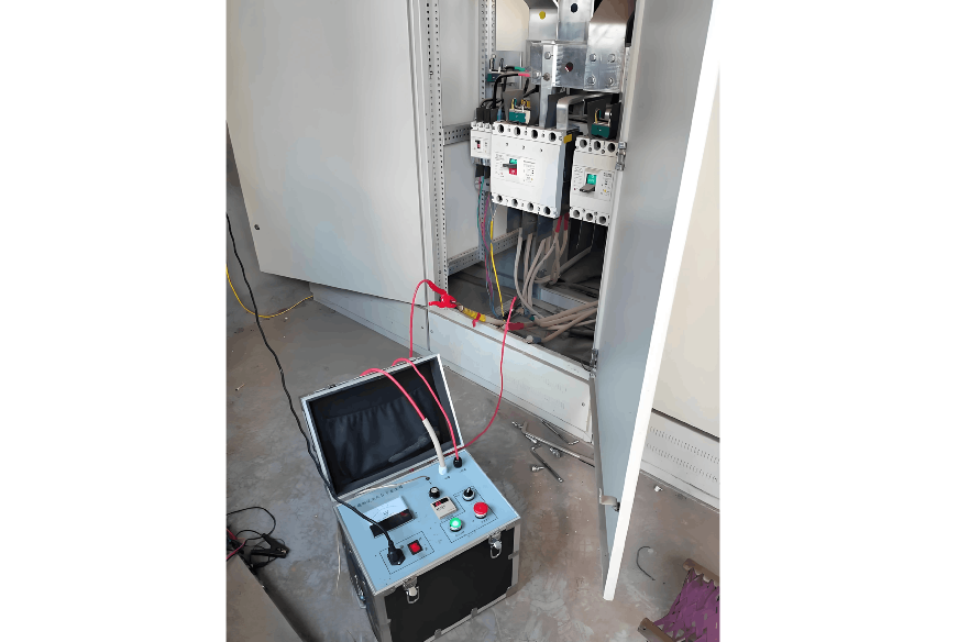
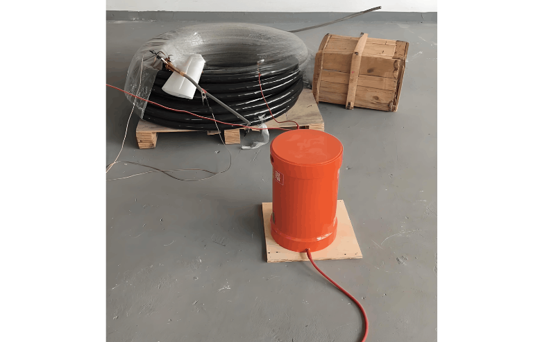
Cable Quality Inspection and Cable Detection & Testing

08/29/2025

Power cable quality inspection and cable testing are conducted to ensure that the cable's quality and performance meet specified requirements, thereby guaranteeing the safe and stable operation of power systems. Below are some common contents of power cable quality inspection and cable testing:

  • Visual Inspection: Check the cable surface for physical defects such as damage, deformation, or scratches to ensure the cable's exterior is intact.
  • Dimensional Measurement: Measure dimensional parameters such as outer diameter, inner diameter, conductor diameter, and insulation thickness to ensure they comply with standard requirements.
  • Thermal and Cold Shock Test: Expose the cable to high and low temperature environments to evaluate its thermal stability and cold rigidity.
  • Nominal Cross-Sectional Area Verification: Use a cable stripper or cross-sectional area measuring instrument to measure the cable’s actual cross-sectional area, ensuring it matches the required nominal value.
  • Resistance Test: Use a resistance tester to measure the cable’s resistance value to verify good conductor contact and ensure resistance complies with standard requirements.
  • Dielectric Loss Factor and Capacitance Test: Use methods such as the dye current method or a dielectric loss tester to measure the cable’s dielectric loss factor and capacitance, assessing the quality of the insulation material.
  • Insulation Resistance Test: Use an insulation resistance tester to measure the resistance of the cable’s insulation, evaluating whether the insulation performance is acceptable and identifying issues such as insulation damage or moisture ingress.

  • High-Voltage Withstand Test: Apply a specified voltage to the cable to verify its insulation capability and dielectric strength.
  • Shielding Effectiveness Test: Use high-frequency or DC methods to test the cable’s shielding effectiveness and evaluate its electromagnetic interference (EMI) resistance.
  • Bending Radius Test: Perform a bending radius test on the cable to ensure its flexibility and bending performance meet requirements.
  • Tensile Strength Test: Conduct a tensile test on the cable to assess its resistance to pulling forces.
  • Cable Joint Test: Measure the contact resistance at cable connection points to verify that connections are secure and reliable, preventing issues such as poor contact or excessive contact resistance.

  • Grounding Test: Measure the grounding resistance of the cable circuit and associated equipment. Proper grounding ensures safety and reduces the risk of insulation breakdown.
  • Leakage Current Test: Use a leakage current meter to measure leakage current in the cable circuit, identifying potential issues such as insulation failure or leakage.
  • Cable Load Test: Perform a load test on the cable circuit to ensure balanced loading and prevent overloading and overheating.
  • Interference Elimination Test: Detect potential interference in the surrounding environment, such as electromagnetic fields or waves, measure signal fluctuations on the cable, and confirm the presence of external interference.
  • Insulation Material Test: Test the insulation material within the cable to evaluate its performance and prevent issues related to aging, degradation, or reduced insulation properties.

The above are common contents of power cable quality inspection and testing. Conducting these tests enables assessment of whether the cable’s quality and performance meet relevant standards and regulations, thus ensuring reliable operation of the cable within power systems.

Hello, my name is Garca. I have 10 years of experience in the power switchgear industry. I specialize in the research, development, and application of switchgear, with in-depth knowledge of high-voltage switch technologies and industry standards. I possess extensive experience in field commissioning and project management, and I am committed to delivering reliable solutions for safe and stable power system operations.

What losses occur during operation of the transformer? How to reduce losses?
Transformers experience various types of losses during operation, primarily categorized into two main types: copper losses and iron losses.Copper LossesCopper losses, also known as I²R losses, are caused by the electrical resistance of the transformer windings—typically made of copper. As current flows through the windings, energy is dissipated in the form of heat. These losses are proportional to the square of the load current (I²R), meaning they increase significantly with high
Rockwell
08/29/2025
Cable Fault Detection, Testing, Location and Repair
I. Methods for Cable Testing and Inspection:Insulation Resistance Test: Use an insulation resistance tester to measure the insulation resistance value of the cable. A high insulation resistance value indicates good insulation, while a low value may suggest insulation problems requiring further investigation.Voltage Withstand Test: Apply a high-voltage test using a high-voltage tester to verify whether the cable can withstand high voltage under its rated operating conditions. Under normal circums
08/29/2025
Transformer Detection, Testing, Maintenance and Servicing
Transformer testing, inspection, and maintenance are essential tasks to ensure normal operation and extend the service life of transformers. Below are some recommended steps:Visual Inspection: Regularly inspect the transformer's exterior, including the enclosure, cooling system, and oil tank. Ensure the enclosure is intact, free from corrosion, damage, or leakage.Insulation Resistance Testing: Use an insulation resistance tester to check the transformer's insulation system. Verify that the insul
Vziman
08/29/2025
Detection, Testing and Comprehensive Monitoring of PV Grid-Connected Cabinets
Photovoltaic (PV) Grid-Connection CabinetA photovoltaic (PV) grid-connection cabinet, also known as a PV grid-connection box or PV AC interface cabinet, is an electrical device used in solar photovoltaic power generation systems. It is primarily responsible for converting the direct current (DC) electricity generated by a PV system into alternating current (AC) and connecting it to the utility grid.Main Components of a PV Grid-Connection Cabinet:DC Input Terminals: Receive DC power generated by
08/28/2025
Inquiry
Download
IEE-Business is dedicated to serving the personnel in the global power industry.
Join IEE-Business, not only can you discover power equipment and power knowledge, but also canhnd like - minded friends!