Nau'o'in Daular HVC da kuma Kirkiro MTDC

Sakamakon Da - Karamin Kirki (HVDC) System Configurations
Sakamakon da - karamin kirki, wanda ake kira HVDC, yana daya daga cikin hanyoyi na biyayya don in tafi kan kirki a gaba - gaban kasa, wanda ya zama da takarda a lalacewa zuwa hukumar da ake amfani da sakamakon da - karamin kasa (AC). An za a yi HVDC system a cikin matsayin abubuwa, kila babban yadda ake bukata saboda abubuwan da suka fi sani. Wannan rubutun yana bayar da tasiri mai sauƙi game da abubuwan da suka fi sani na system configurations na HVDC.
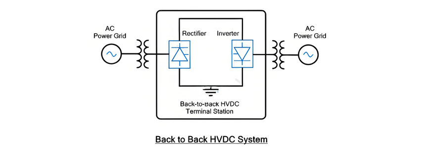
Back - to - Back HVDC Systems
A cikin sakamakon da - karamin back - to - back (B2B) HVDC, wadannan rectifier da inverter, wadanda su ne muhimman abubuwan na converter, suna cikin terminal station na baya. Wadannan abubuwan suka shiga zama da karamin kasa a cikin terminal station. Bayanin mafi inganci na wannan configuration shine don in taka rawa a kan AC power systems biyu. Yana yi wannan tushen rawa ta hanyar in canza AC power na gaba - gaban zuwa DC ta hanyar rectifier, kuma bincika DC power na gaba - gaban zuwa AC ta hanyar inverter.
Back - to - Back HVDC Systems (Continued)
An samu sakamakon da - karamin back - to - back HVDC a cikin room na baya, wanda yake taka rawa a kan AC power systems biyu da ba su sama frequency. Saboda in shiga zama da karamin kasa na rectifier da inverter, ba a duba DC transmission line ba. Don in tsara waɗannan thyristors da suka shiga zama da karamin kasa, an iya haɓaka voltage na DC da ke sa a lage da rai. Duk da haka, rating na current na configuration yana iya haɗa zuwa almudunan amperes.
Wannan type na HVDC system yana da muhimmanci musamman don in taka rawa a kan AC power systems biyu a cikin al'adun da suka fi sani:
Two - Terminal HVDC System
A cikin two - terminal HVDC configuration, akwai terminal stations biyu, kila wanda yana taimaka don converter station. Wanda ake ciki na rectifier, kuma wanda ake ciki na inverter. Wadannan terminals suna shiga zama da karamin kasa ta hanyar HVDC transmission line, wanda yana taimaka don in tafi kan kirki a gaba - gaban kasa da biyayya. Wannan setup yana taimaka don in kawo kwalbar da ake amfani da AC transmission don in tafi kan kirki a gaba - gaban kasa, wanda yana taimaka don in haɗa lalacewar da ake amfani da DC power don in haɗa lalacewar da ake amfani da AC power.
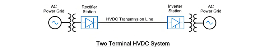
System na two - terminal HVDC yana da shiga zama da karamin kasa a kan biyu points bayan da ba suka duba parallel transmission lines ko intermediate taps a cikin transmission line. Wannan yadda yake taimaka don in bayyana shi a kan point - to - point power transmission. Yana da muhimmanci musamman don in tafi kan kirki a kan biyu locations da ba su sama da gaba - gaban kasa.
Wannan muhimman faɗa na system na two - terminal HVDC shine ba suka duba HVDC circuit breaker. Idan ake yi maintenance ko idan ake kawo fault, an iya amfani da AC circuit breakers a cikin AC side don in kawo energy na DC line. Duk da haka, AC circuit breakers suna da design da yake tsari da kuma mutane da ke karfi, wanda yana taimaka don in zama da system na two - terminal HVDC da yake tsari da kuma mutane da ke karfi.
Multi - Terminal DC (MTDC) System
System na Multi - Terminal DC (MTDC) yana nuna configuration na HVDC da ke da muhimmiyar. Yana amfani da multiple transmission lines don in taka rawa a kan kadan points. Wannan setup yana da terminal stations biyu, kila wanda yana taimaka don converter, wadanda su shiga zama da karamin kasa ta hanyar network na HVDC transmission line. A cikin wannan network, wasu converters suna yi waɗannan rectifiers, wanda suke canza AC power zuwa DC, kuma wasu suna yi waɗannan inverters, wanda suke canza DC power zuwa AC don in tafi kan zuwa loads. Muhimman principle na MTDC system shine cewa total power na rectifier stations yana da kyau da combined power na inverter (load) stations, wanda yana taimaka don in taka rawa da flow na power na network na interconnected.
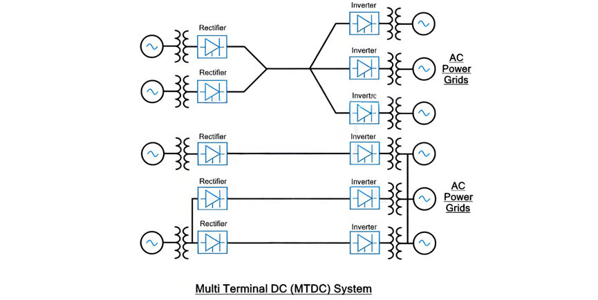
Multi - Terminal DC (MTDC) System (Continued)
Network na MTDC yana da flexibility kamar grid na AC, amma yana da faɗa mai ma'ana: ability na precise control na power flow a cikin network na DC distributed. Amma, wannan faɗa mai ma'ana yana da cost na increased complexity, wanda yana taimaka don in zama da system na MTDC da ke da muhimmiyar da yake tsari.
A cikin setup na MTDC, ba a zama da amfani da AC circuit breakers a cikin AC side. Ba a zama da amfani da AC circuit breaker a cikin system na two - terminal, ita ce de - energize entire DC network ba kuɗi isolating faulty or maintenance - required line. Don in kawo wannan, system na MTDC yana buƙata multiple DC switchgear components, kamar circuit breakers. Wadannan specialized DC circuit breakers suna da design don in kawo circuits ko isolate specific sections a lokacin maintenance operations ko kuma idan ake kawo fault, wanda yana taimaka don in taka rawa da stability and reliability na network.
Maintaining balance na system yana da muhimmanci a cikin system na MTDC. Total current na rectifier stations yana da kyau da current consumed na inverter stations. Idan ake kawo surge na power demand na inverter station, DC power output yana buƙata ramp up accordingly to meet the increased load. A lokacin wannan process, ita ce da kyau a close monitor and control both the supplied voltage and the operation of the inverters to prevent overloading, which could lead to system failures.
Wannan muhimman faɗa na system na MTDC shine reliability during forced outages. Idan ake kawo unexpected power failure na one of the generation stations, system yana iya quick re - route power through alternative converter stations, minimizing disruption to the overall power supply.
Applications of MTDC
Systems na MTDC zai iya kategorizawa a matsayin biyu primary types:
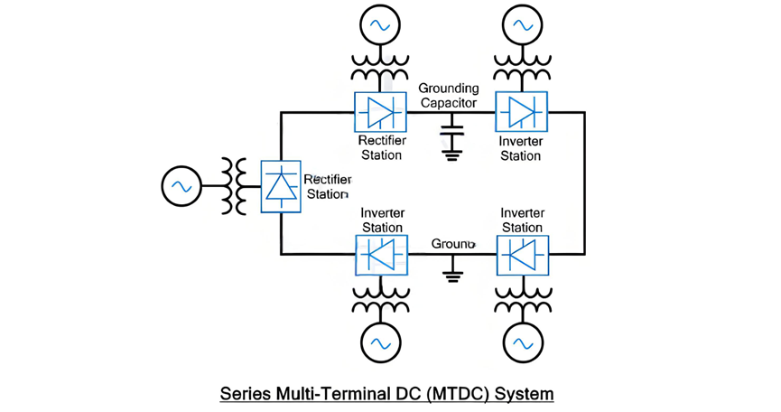
Series MTDC System
A cikin series MTDC configuration, multiple converter stations suna shiga zama da karamin kasa, kamar components a cikin electrical series circuit. Defining characteristic na wannan setup shine cewa current flowing through each converter station remains identical, as it is set by one of the stations. Amma, voltage drop yana shirin a cikin converter stations, kila wanda yana da portion of the total voltage drop across the series - connected network.
Series MTDC System (Continued)
System na series MTDC zai iya ɗaukan version na extended na system na two - terminal HVDC, wanda yana amfani da multiple converter stations connected in series, kamar yadda aka bayyana a cikin diagram. Typically, converter stations a cikin setup na series MTDC suna da lower capacity compared to those utilized in parallel MTDC systems.
Wannan system commonly employs monopolar DC links, where the DC line is grounded at only one specific point. To safeguard against transient electrical surges, a grounding capacitor can be installed at other points along the line as an additional protective measure.
Insulation coordination in the series MTDC system presents significant challenges due to the varying DC voltages at each station. The power flow control mechanism in the series MTDC system is more intricate compared to that of the parallel MTDC system. In a parallel MTDC system, power flow can be regulated by injecting current into specific lines, whereas in the series MTDC system, power flow control relies on adjusting the voltage at each terminal station.
Power flow reversal in a series MTDC system can be readily achieved using both Voltage Source Converters (VSC) and Current Source Converters (CSC). However, when a fault occurs or scheduled maintenance is required for a particular line, the entire DC network will experience a blackout. Similar to the two - terminal HVDC system, AC - side circuit breakers are employed to de - energize the DC network. Expanding the series MTDC system also poses difficulties. Installing new terminal stations necessitates a complete blackout of the network, as the ring - shaped DC network must be split at the installation point, disrupting power supply to all other stations along the path.
Parallel MTDC System
In a parallel MTDC system, multiple converter stations functioning as inverters or load stations are connected to a single converter station acting as a rectifier. This rectifier station supplies power to the entire DC network. Analogous to a parallel electrical circuit, the voltage remains constant across all inverter or load stations, with its value set by one of the converter stations. In contrast, the current supply varies according to the power demand at each station. To maintain a balanced current supply, the current is dynamically adjusted in response to the power requirements of individual load stations. Generally, the terminal stations in a parallel MTDC system have a higher capacity than those in a series MTDC network.
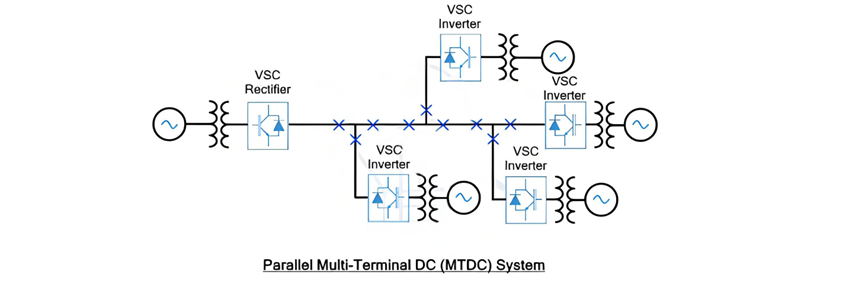
Parallel MTDC System (Continued)
Power reversal in a parallel MTDC system can be accomplished through either voltage reversal or current reversal methods. When using voltage reversal, which is typically associated with Current Source Converter (CSC) - based terminal stations, it has an impact on all converter stations. As a result, a highly sophisticated control and communication system must be implemented among these converters to manage this effect. On the other hand, if power reversal is achieved using the current reversal technique, which is often associated with Voltage Source Converter (VSC) - based terminal stations, the process is much more straightforward to execute. This is the primary reason why VSCs are favored over CSCs in parallel MTDC systems.
In a VSC - based MTDC system, since the voltage remains constant, the power rating of the terminal station is determined by the current ratings of the valve converter. This configuration offers a significant advantage in terms of power flow control within the DC network. It can precisely regulate the power flow by injecting current into specific lines, which is a more convenient approach compared to the power control mechanism in series systems that rely on voltage control at each station.
One of the most notable features of the parallel MTDC system is its resilience in the face of faults. If a fault occurs in any of the terminal stations, the remainder of the DC network remains unaffected. However, to isolate the specific DC lines associated with the faulty station, a separate DC circuit breaker is required. Additionally, during the expansion of the DC network, there is no need to interrupt the power supply. This is because new terminal stations can be installed in parallel with the existing lines, ensuring seamless integration without disrupting the ongoing power distribution.
Another advantage of the parallel MTDC system is its relatively simple insulation coordination compared to a series system. Due to the constant voltage across the network, the insulation requirements are more straightforward to manage.
The parallel MTDC system can be further classified into two categories:
Radial MTDC System
The radial MTDC system is a specific type of parallel MTDC configuration. In this setup, if there is a break in a transmission line or the removal of one link, it will lead to the interruption of power supply to one or more converter stations. This characteristic makes the radial MTDC system somewhat vulnerable to single - point - of - failure scenarios, as any disruption in the transmission line can have a direct impact on the power supply to certain parts of the network.
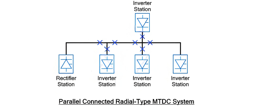
The provided figure depicts a configuration where four inverter stations are connected to a single rectifier station. In this setup, it is evident that if there is a break in any one of the lines, it will inevitably result in the interruption of power supply to at least one terminal station. This vulnerability makes the radial MTDC system less reliable when compared to the Mesh or Ring type MTDC systems.
Mesh (Ring) MTDC System
In a Mesh or Ring MTDC system, the inverter (load) stations are interconnected with a single rectifier station in a mesh or ring - like formation. One of the key advantages of this configuration is that even if there is a break in a single transmission line or the removal of one link, it does not lead to the interruption of power supply to any of the inverter stations. The subsequent figure clearly illustrates such a mesh or ring MTDC system. This inherent resilience to line failures makes the Mesh or Ring MTDC system a more reliable option for power transmission and distribution in certain applications, as it can better withstand disruptions and ensure continuous power supply to the connected load stations.
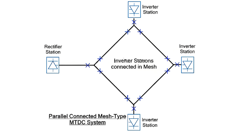
As illustrated, in a mesh or ring - type MTDC system, the removal of any single link does not disrupt the power supply to any converter station. Instead, the electrical power is automatically rerouted through alternative links within the network. This seamless redirection is made possible by the interconnected nature of the mesh or ring configuration. However, it is crucial to note that these alternative links must be meticulously designed to handle the increased power transmission while minimizing power losses.
The absence of power interruptions in the mesh - type MTDC system is a significant advantage. It ensures a continuous and stable power supply, even in the face of unexpected link failures. Consequently, a parallel - connected mesh - type MTDC system offers superior reliability compared to its parallel - connected radial - type counterpart. The radial system's susceptibility to power outages due to single - link disruptions pales in comparison to the mesh system's robust ability to maintain power flow under similar circumstances, making the mesh or ring - type MTDC system a preferred choice for applications where uninterrupted power delivery is of utmost importance.
Tambayar Da Yawanci


