Mga Tipo sa HVDC Systems ug MTDC Configurations

Konfigurasyon sa Sistema sa High - Voltage Direct Current (HVDC)
Ang High - Voltage Direct Current, nga kasagaran gipangutana isip HVDC, usa ka napakamaayong paagi sa pagpadala og kuryente sa dako nga distansya, nga nagbawas sa mubo nga nawala sa kuryente kumpara sa tradisyonal nga alternating - current (AC) transmission. Ang sistema sa HVDC mahimo molihok sa daghang konfigurasyon, bawgad ang bawgad naglalain sa partikular nga pangangailangan sa operasyon. Ang artikulo niini naghatag og maong overview sa pangunahan nga mga tipo sa konfigurasyon sa sistema sa HVDC.
Back - to - Back HVDC Systems
Sa back - to - back (B2B) HVDC configuration, ang parehas nga rectifier ug inverter, nga ang duha ka key component sa converter, nahimutang sa parehas nga terminal station. Kini duha ka elemento sa converter direktang gipangandam back - to - back sa uban. Ang primary function niining konfigurasyon mao ang pagkonekta sa duha ka separate AC power systems. Nagbuhat kini pinaagi sa pag-convert sa ingong AC power ngadto sa DC pinaagi sa rectifier ug pagkatapos molihok sa DC power ngadto sa AC gamit ang inverter.
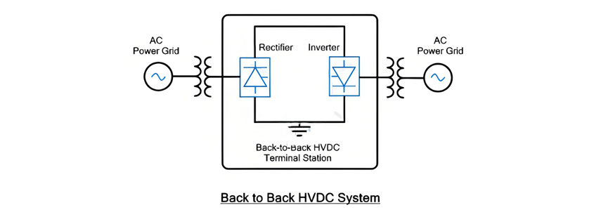
Back - to - Back HVDC Systems (Continued)
Ang setup sa back - to - back HVDC gitukod sa usa ka room ug nagserbisyo aron makonekta ang duha ka asynchronous AC power systems. Tungod sa direct back - to - back connection sa rectifier ug inverter, wala na ang pangangailangan alang sa DC transmission line. Aron mapahimulos ang bilang sa thyristors nga gipangandam sa series, ang intermediate DC voltage naintindihan sa low level. Sa panahon, ang current rating niining konfigurasyon mahimo magabot sa pipila ka libo amperes.
Kini tipo sa sistema sa HVDC labi ka useful sa pagkonekta sa duha ka asynchronous AC power systems sa sumala nga mga scenario:
Two - Terminal HVDC System
Sa two - terminal HVDC configuration, adunay duha ka distinct terminal stations, bawgad nagfunction isip converter station. Ang usa ka station nahimutang ang rectifier, samtang ang uban nag-inverter. Kini duha ka terminals gipangandam pinaagi sa HVDC transmission line, nga nagpadala sa efficient transmission sa electrical power sa dako nga distansya. Kini setup gidisenyo aron mobati sa mga limitasyon sa tradisyonal nga AC transmission sa long - haul power transfer, paggamit sa advantages sa DC power aron mapahimulos ang power losses ug i-boost ang transmission efficiency sa dako nga geographical areas.
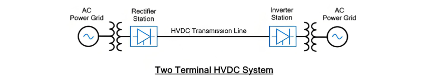
Ang two - terminal HVDC system may feature sa direct connection tali sa duha ka points wala na ang parallel transmission lines o intermediate taps tali sa transmission line. Kini characteristic naghatag og alternative name, point - to - point power transmission. Kini ideal para sa power supply applications tali sa duha ka locations nga geographically distant gikan sa uban.
Usa sa notable advantages sa two - terminal HVDC system mao ang wala na ang requirement alang sa HVDC circuit breaker. Sa panahon sa maintenance o sa pag-clear sa faults, ang AC circuit breakers sa AC side mahimong gamiton aron de - energize ang DC line. Kumpara sa DC circuit breakers, ang AC circuit breakers adunay mas simple nga disenyo ug mas murano, nagpadayon sa two - terminal HVDC system mas economical ug mas easy to maintain.
Multi - Terminal DC (MTDC) System
Ang Multi - Terminal DC (MTDC) system represent sa mas komplikado nga HVDC configuration. Igi employ multiple transmission lines aron makonekta ang higayon pa sa duha ka points. Kini setup adunay daghang terminal stations, bawgad nag-equipped sa ilang kaugalingon nga converter, tanang gipangandam pinaagi sa HVDC transmission line network. Sa sulod niining network, ang pipila ka converters nagfunction isip rectifiers, nga nag-convert sa AC power ngadto sa DC, samtang ang uban nagoperate isip inverters, nga nag-transform sa DC power ngadto sa AC para sa distribution sa loads. Ang fundamental principle sa MTDC system mao ang total power supplied sa rectifier stations kinahanglan equal sa combined power received sa inverter (load) stations, nagaseguro sa balanced ug efficient power flow sa interconnected network.
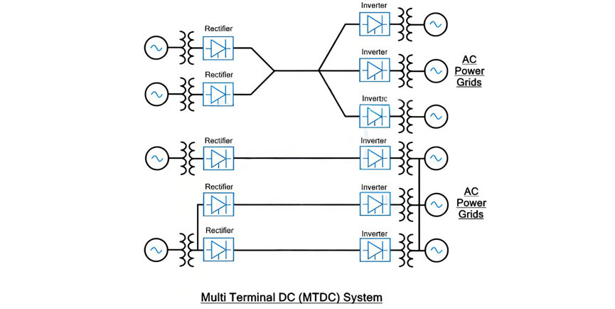
Multi - Terminal DC (MTDC) System (Continued)
Ang MTDC network analogous sa AC grid sa term sa flexibility, apan adunay unique advantage: ang ability sa precise control sa power flow sa DC distributed network. Subong, kini enhanced functionality adunay cost sa increased complexity, nagpadayon sa MTDC system significantly mas intricate kay sa two - terminal HVDC configuration.
Sa MTDC setup, ang pag-dependi sa AC circuit breakers sa AC side wala na feasible. Wala sa two - terminal system, ang paggamit sa AC circuit breaker de - energize ang entire DC network wala ra ang isolation sa faulty o maintenance - required line. Aron address kini, ang MTDC system necessitates multiple DC switchgear components, sama sa circuit breakers. Kini specialized DC circuit breakers designed aron safe de - energize circuits o isolate specific sections sa panahon sa maintenance operations o sa pag-clear sa faults, nagaseguro sa stability ug reliability sa network.
Maintaining system balance crucial sa MTDC system. Ang total current supplied sa rectifier stations kinahanglan precisely match sa current consumed sa inverter stations. Kon adunay sudden surge sa power demand gikan sa any inverter station, ang DC power output needs to be ramped up accordingly aron mapahimulos ang increased load. Sa panahon sa proseso, essential closely monitor ug control both the supplied voltage ug operation sa inverters aron prevent overloading, nga could lead to system failures.
Usa sa key strengths sa MTDC systems mao ang reliability sa forced outages. Sa panahon sa unexpected power failure sa one of the generation stations, ang system can quickly re - route power through alternative converter stations, minimizing disruption sa overall power supply.
Applications of MTDC
MTDC systems can be categorized into two primary types:
Series MTDC System
In a series MTDC configuration, multiple converter stations are connected in series, much like components in an electrical series circuit. A defining characteristic of this setup is that the current flowing through each converter station remains identical, as it is set by one of the stations. However, the voltage drop is distributed among the converter stations, with each station experiencing a portion of the total voltage drop across the series - connected network.
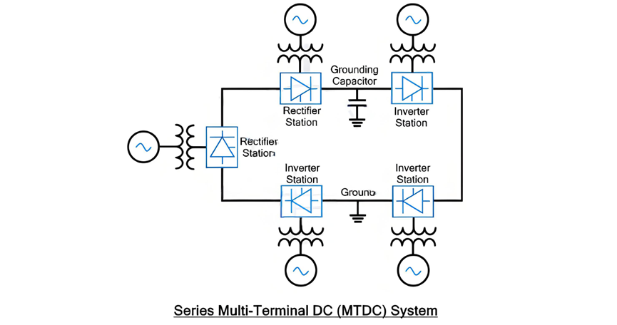
Series MTDC System (Continued)
The series MTDC system can be regarded as an extended version of the two - terminal HVDC system, incorporating multiple converter stations connected in series, as illustrated in the accompanying diagram. Typically, the converter stations in a series MTDC setup have a lower capacity compared to those utilized in parallel MTDC systems.
This system commonly employs monopolar DC links, where the DC line is grounded at only one specific point. To safeguard against transient electrical surges, a grounding capacitor can be installed at other points along the line as an additional protective measure.
Insulation coordination in the series MTDC system presents significant challenges due to the varying DC voltages at each station. The power flow control mechanism in the series MTDC system is more intricate compared to that of the parallel MTDC system. In a parallel MTDC system, power flow can be regulated by injecting current into specific lines, whereas in the series MTDC system, power flow control relies on adjusting the voltage at each terminal station.
Power flow reversal in a series MTDC system can be readily achieved using both Voltage Source Converters (VSC) and Current Source Converters (CSC). However, when a fault occurs or scheduled maintenance is required for a particular line, the entire DC network will experience a blackout. Similar to the two - terminal HVDC system, AC - side circuit breakers are employed to de - energize the DC network. Expanding the series MTDC system also poses difficulties. Installing new terminal stations necessitates a complete blackout of the network, as the ring - shaped DC network must be split at the installation point, disrupting power supply to all other stations along the path.
Parallel MTDC System
In a parallel MTDC system, multiple converter stations functioning as inverters or load stations are connected to a single converter station acting as a rectifier. This rectifier station supplies power to the entire DC network. Analogous to a parallel electrical circuit, the voltage remains constant across all inverter or load stations, with its value set by one of the converter stations. In contrast, the current supply varies according to the power demand at each station. To maintain a balanced current supply, the current is dynamically adjusted in response to the power requirements of individual load stations. Generally, the terminal stations in a parallel MTDC system have a higher capacity than those in a series MTDC network.
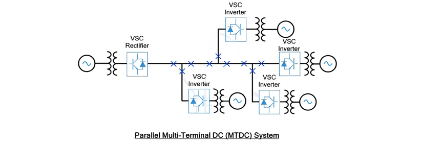
Parallel MTDC System (Continued)
Power reversal in a parallel MTDC system can be accomplished through either voltage reversal or current reversal methods. When using voltage reversal, which is typically associated with Current Source Converter (CSC) - based terminal stations, it has an impact on all converter stations. As a result, a highly sophisticated control and communication system must be implemented among these converters to manage this effect. On the other hand, if power reversal is achieved using the current reversal technique, which is often associated with Voltage Source Converter (VSC) - based terminal stations, the process is much more straightforward to execute. This is the primary reason why VSCs are favored over CSCs in parallel MTDC systems.
In a VSC - based MTDC system, since the voltage remains constant, the power rating of the terminal station is determined by the current ratings of the valve converter. This configuration offers a significant advantage in terms of power flow control within the DC network. It can precisely regulate the power flow by injecting current into specific lines, which is a more convenient approach compared to the power control mechanism in series systems that rely on voltage control at each station.
One of the most notable features of the parallel MTDC system is its resilience in the face of faults. If a fault occurs in any of the terminal stations, the remainder of the DC network remains unaffected. However, to isolate the specific DC lines associated with the faulty station, a separate DC circuit breaker is required. Additionally, during the expansion of the DC network, there is no need to interrupt the power supply. This is because new terminal stations can be installed in parallel with the existing lines, ensuring seamless integration without disrupting the ongoing power distribution.
Another advantage of the parallel MTDC system is its relatively simple insulation coordination compared to a series system. Due to the constant voltage across the network, the insulation requirements are more straightforward to manage.
The parallel MTDC system can be further classified into two categories:
Radial MTDC System
The radial MTDC system is a specific type of parallel MTDC configuration. In this setup, if there is a break in a transmission line or the removal of one link, it will lead to the interruption of power supply to one or more converter stations. This characteristic makes the radial MTDC system somewhat vulnerable to single - point - of - failure scenarios, as any disruption in the transmission line can have a direct impact on the power supply to certain parts of the network.
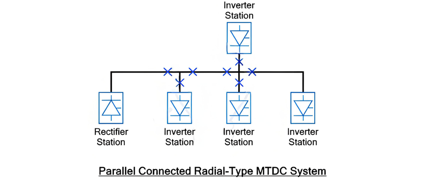
The provided figure depicts a configuration where four inverter stations are connected to a single rectifier station. In this setup, it is evident that if there is a break in any one of the lines, it will inevitably result in the interruption of power supply to at least one terminal station. This vulnerability makes the radial MTDC system less reliable when compared to the Mesh or Ring type MTDC systems.
Mesh (Ring) MTDC System
In a Mesh or Ring MTDC system, the inverter (load) stations are interconnected with a single rectifier station in a mesh or ring - like formation. One of the key advantages of this configuration is that even if there is a break in a single transmission line or the removal of one link, it does not lead to the interruption of power supply to any of the inverter stations. The subsequent figure clearly illustrates such a mesh or ring MTDC system. This inherent resilience to line failures makes the Mesh or Ring MTDC system a more reliable option for power transmission and distribution in certain applications, as it can better withstand disruptions and ensure continuous power supply to the connected load stations.
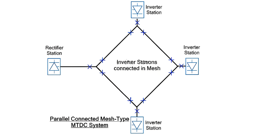
As illustrated, in a mesh or ring - type MTDC system, the removal of any single link does not disrupt the power supply to any converter station. Instead, the electrical power is automatically rerouted through alternative links within the network. This seamless redirection is made possible by the interconnected nature of the mesh or ring configuration. However, it is crucial to note that these alternative links must be meticulously designed to handle the increased power transmission while minimizing power losses.
The absence of power interruptions in the mesh - type MTDC system is a significant advantage. It ensures a continuous and stable power supply, even in the face of unexpected link failures. Consequently, a parallel - connected mesh - type MTDC system offers superior reliability compared to its parallel - connected radial - type counterpart. The radial system's susceptibility to power outages due to single - link disruptions pales in comparison to the mesh system's robust ability to maintain power flow under similar circumstances, making the mesh or ring - type MTDC system a preferred choice for applications where uninterrupted power delivery is of utmost importance.
Mahitungod sa mga eksperto
Gipareserbado


