Electrical Transmission Networks – EHV and HV Overhead Lines

Electrical Transmission Networks and Overhead Lines
In electrical power systems, Extra High Voltage (EHV, where the voltage V≥150 kV and High Voltage (HV, with 60 kV ≤ V <150 kV) are commonly employed for energy transmission. The use of these high - voltage levels serves to reduce the current flowing through the transmission lines. According to Joule's law, W=RI2t=UIt, where W represents the energy dissipated as heat, R is the resistance of the conductor, I is the current, t is the time, and U is the voltage. By decreasing the current, it becomes possible to reduce the cross - section of the conductors, thereby also minimizing power losses due to the Joule effect.
Transmission networks typically originate from power stations and substations. While overhead lines are the predominant component in many areas, in urban settings, underground insulated cables are often a necessity due to space constraints and aesthetic considerations.
EHV and HV overhead lines are primarily composed of the following key elements:
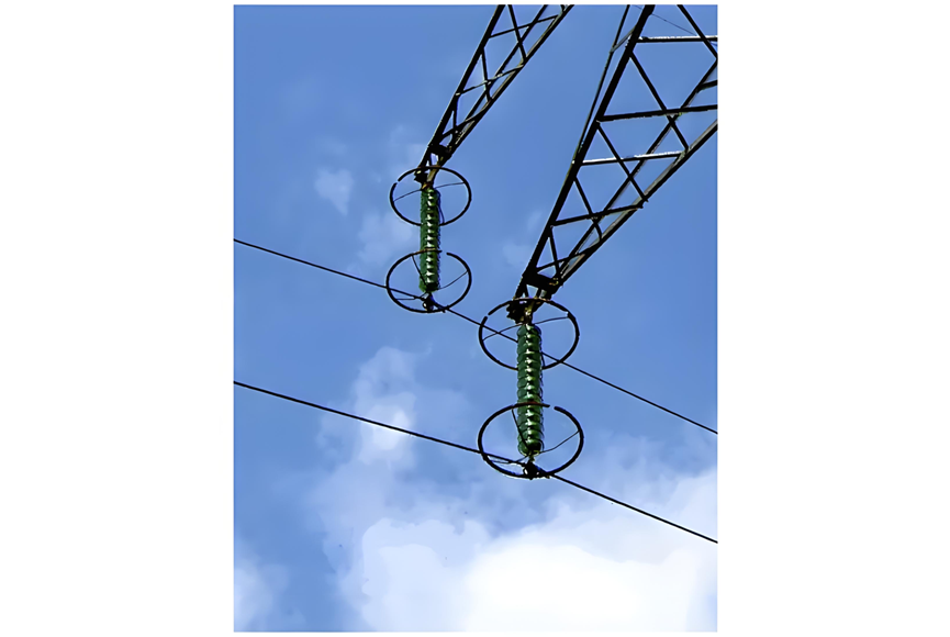
Power transmission equipment is engineered with the goal of minimizing the formation of corona discharge. Corona rings, as depicted in Figure 1, play a crucial role in this regard. By spreading the electric field over a larger area, they reduce the field gradient below the corona threshold, effectively suppressing corona discharge. This not only helps to prevent power losses associated with corona but also reduces audible noise and electromagnetic interference, contributing to the overall efficiency and reliability of the transmission system.
Protection Against Lightning for Overhead Lines and the Role of OPGW Cables
One of the most significant threats to overhead lines is lightning. These lines are exposed to the risk of lightning strikes throughout their entire length, which means that the protection provided solely by surge arresters at substations is insufficient. Additional safeguarding measures are essential to ensure the reliability and safety of the transmission system.
To address this issue, "lightning aerial protection wires" are installed along the entire route of overhead lines. Among these, Optical Power Ground Wire (OPGW) cables are widely utilized due to their dual functionality. An OPGW cable features a tubular structure that houses one or more optical single - mode fibers at its core. This central fiber assembly is then surrounded by multiple layers of steel and aluminium wires.
The conductive outer layers of the OPGW cable serve a crucial purpose in electrical protection. They connect adjacent transmission towers to the ground, creating a low - resistance pathway for lightning currents. By doing so, they effectively shield the power conductors from direct lightning strikes, reducing the likelihood of damage to the main transmission lines.
Simultaneously, the optical fibers within the OPGW cable offer significant communication advantages. These fibers can be employed for high - speed data transmission, fulfilling various needs within the electrical utility sector. They are used for internal applications such as the protection and control of transmission lines, enabling real - time monitoring and quick response to potential issues. Additionally, they support voice and data communication requirements, facilitating seamless coordination among different parts of the power grid.
The optical fibers themselves possess excellent insulating properties, which provide inherent protection against electrical induction from the power transmission lines and lightning. They are also highly resistant to external noise and cross - talk, ensuring the integrity of the transmitted data. Moreover, optical fibers have extremely low transmission losses, making them ideal for long - distance, high - speed data transfer without significant signal degradation.
Figure 2 illustrates a typical example of an OPGW cable, showcasing its unique structure and highlighting how it combines electrical protection and communication capabilities, making it an indispensable component in modern overhead transmission line systems.

In certain countries, for older overhead lines operating at a voltage level of 72.5 kV, a particular approach to lightning protection was once in use. Historically, only the first four or five spans adjacent to substations were equipped with protective measures, and Aluminium Conductor Steel - Reinforced (ACSR) cables were employed for this purpose. However, this solution has now been phased out. The Optical Power Ground Wire (OPGW) cable has become the preferred choice, as it not only offers effective lightning protection but also enables data communication between substations, providing a more comprehensive and versatile solution.
Insulated cables commonly feature cross - linked polyethylene (XLPE) insulation. These cables typically have aluminium conductors and are designed for single - phase applications. The use of XLPE insulation provides excellent electrical properties, mechanical strength, and durability, making it well - suited for power transmission.
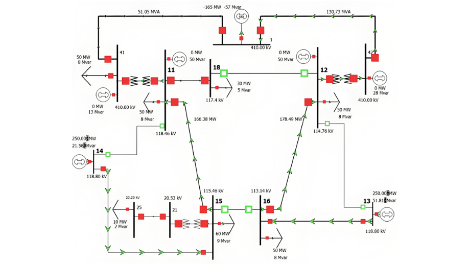
Extra High Voltage (EHV) and High Voltage (HV) transmission networks often adopt a "ring" configuration. As depicted in Figure 3, this setup is characterized by a significant degree of complexity. The ring configuration offers enhanced reliability and flexibility in power distribution, allowing for better load sharing and easier maintenance and operation of the network. It enables power to be rerouted in case of a fault or maintenance work, minimizing disruptions to the power supply and ensuring a more stable and efficient transmission system.
Recommended


