Percentage Differential Relay

Definition: A percentage differential relay is defined as a type of relay that functions based on the phase difference of two or more similar electrical quantities. It represents an advanced form of differential protection relay. The sole distinction between it and other differential relays lies in the presence of a restraining coil. The percentage differential relay incorporates a restraining coil precisely to address issues stemming from discrepancies in the current ratio when dealing with high - magnitude external short - circuit currents.
The percentage differential system features a restraining coil connected within the pilot wire, as depicted in the figure below. The currents induced in both current transformers (CTs) flow through this restraining coil. Meanwhile, the operating coil is positioned at the mid - point of the restraining coil.
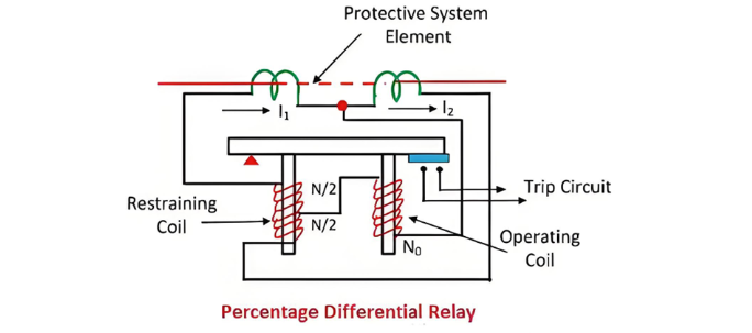
The restraining coil governs the sensitive characteristic of the relay. It serves to prevent the transformer from tripping undesirably as a result of unbalanced currents. Additionally, the restraining coil mitigates harmonics present in the inrush current.
Working Principle of the Percentage Differential Relay
The torque generated by the restraining coil acts to prevent the closure of the trip circuit, whereas the torque from the operating coil attempts to close the contacts of the trip circuit. Under normal operating conditions and during through - load scenarios, the torque produced by the restraining coil exceeds that of the operating coil. Consequently, the relay remains in a non - operative state.
When an internal fault occurs, the operating torque surpasses the restraining torque. At this point, the contacts of the trip circuit close, thereby opening the circuit breaker. The restraining torque can be adjusted by altering the number of turns of the restraining coil.

Due to the influence of the restraining coil, the differential current required for the operation of this relay is a variable quantity. The differential current in the operating coil is proportional to (I1 - I2). Since the operating current is connected to the midpoint of the restraining coil, the current in the restraining coil is proportional to (I1 + I2)/2. During external faults, both I1 and I2 increase, leading to an increase in the restraining torque. This effectively prevents the relay from malfunctioning.
Operating Characteristic of the Percentage Differential Relay
The operating characteristic of the percentage differential relay is illustrated in the figure below. The graph clearly demonstrates that the ratio of the operating current to the restraining current remains at a fixed percentage. This type of relay is also known as the biased differential relay. The reason is that the restraining coil is often referred to as a bias coil, as it generates additional magnetic flux, influencing the relay's operation.

Types of Percentage Differential Relay
The percentage differential relay is mainly categorized into two types, namely:
These relays are employed for the protection of various electrical components such as generators, transformers, feeders, transmission lines, and so on.
1. Three - Terminal System Application
This type of percentage differential relay can be utilized for electrical elements with more than two terminals. In a three - terminal configuration, each terminal is associated with a coil having an equal number of turns. The torques generated by these coils act independently of one another and are combined arithmetically.

The percentage slope characteristic of the relay varies according to the current distribution among the restraining coils. These relays are designed to operate instantaneously or at high speeds, enabling rapid response to abnormal conditions.
2. Induction - Type Biased Differential Relay
The induction - type biased differential relay features a pivoted disc that moves within the air gaps of two electromagnets. A copper ring is attached to a portion of each pole, and this ring has the ability to move towards, into, or away from the pole. This mechanical arrangement plays a crucial role in the relay's operation, allowing it to detect differences in electrical quantities and trigger protective actions when necessary.

The disc is subjected to two distinct torques: one generated by the operating element and the other by the restraining element. When the shading rings of both elements are positioned identically, the restraining torque acting on the ring becomes zero. However, when the shading ring of the restraining element is shifted deeper into the iron core, the torque exerted by the restraining element surpasses that of the operating torque.