• Product
  • Suppliers
  • Manufacturers
  • Solutions
  • Free tools
  • Knowledges
  • Experts
  • Communities
Search


Percentage Differential Relay

Edwiin
Field: Power switch
China

Definition: A percentage differential relay is defined as a type of relay that functions based on the phase difference of two or more similar electrical quantities. It represents an advanced form of differential protection relay. The sole distinction between it and other differential relays lies in the presence of a restraining coil. The percentage differential relay incorporates a restraining coil precisely to address issues stemming from discrepancies in the current ratio when dealing with high - magnitude external short - circuit currents.

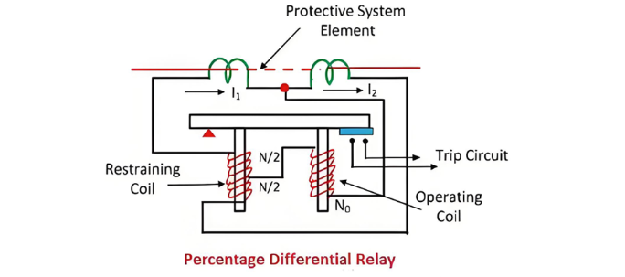
The percentage differential system features a restraining coil connected within the pilot wire, as depicted in the figure below. The currents induced in both current transformers (CTs) flow through this restraining coil. Meanwhile, the operating coil is positioned at the mid - point of the restraining coil.

The restraining coil governs the sensitive characteristic of the relay. It serves to prevent the transformer from tripping undesirably as a result of unbalanced currents. Additionally, the restraining coil mitigates harmonics present in the inrush current.
 
Working Principle of the Percentage Differential Relay
The torque generated by the restraining coil acts to prevent the closure of the trip circuit, whereas the torque from the operating coil attempts to close the contacts of the trip circuit. Under normal operating conditions and during through - load scenarios, the torque produced by the restraining coil exceeds that of the operating coil. Consequently, the relay remains in a non - operative state.
When an internal fault occurs, the operating torque surpasses the restraining torque. At this point, the contacts of the trip circuit close, thereby opening the circuit breaker. The restraining torque can be adjusted by altering the number of turns of the restraining coil.
Due to the influence of the restraining coil, the differential current required for the operation of this relay is a variable quantity. The differential current in the operating coil is proportional to (I1 - I2). Since the operating current is connected to the midpoint of the restraining coil, the current in the restraining coil is proportional to (I1 + I2)/2. During external faults, both I1 and I2 increase, leading to an increase in the restraining torque. This effectively prevents the relay from malfunctioning.
 
Operating Characteristic of the Percentage Differential Relay
The operating characteristic of the percentage differential relay is illustrated in the figure below. The graph clearly demonstrates that the ratio of the operating current to the restraining current remains at a fixed percentage. This type of relay is also known as the biased differential relay. The reason is that the restraining coil is often referred to as a bias coil, as it generates additional magnetic flux, influencing the relay's operation.
Types of Percentage Differential Relay
The percentage differential relay is mainly categorized into two types, namely:
  • The application of the percentage differential relay in a three - terminal system.
  • The induction - type biased differential relay.
These relays are employed for the protection of various electrical components such as generators, transformers, feeders, transmission lines, and so on.
 
1. Three - Terminal System Application
This type of percentage differential relay can be utilized for electrical elements with more than two terminals. In a three - terminal configuration, each terminal is associated with a coil having an equal number of turns. The torques generated by these coils act independently of one another and are combined arithmetically.
The percentage slope characteristic of the relay varies according to the current distribution among the restraining coils. These relays are designed to operate instantaneously or at high speeds, enabling rapid response to abnormal conditions.
 
2. Induction - Type Biased Differential Relay
The induction - type biased differential relay features a pivoted disc that moves within the air gaps of two electromagnets. A copper ring is attached to a portion of each pole, and this ring has the ability to move towards, into, or away from the pole. This mechanical arrangement plays a crucial role in the relay's operation, allowing it to detect differences in electrical quantities and trigger protective actions when necessary.
The disc is subjected to two distinct torques: one generated by the operating element and the other by the restraining element. When the shading rings of both elements are positioned identically, the restraining torque acting on the ring becomes zero. However, when the shading ring of the restraining element is shifted deeper into the iron core, the torque exerted by the restraining element surpasses that of the operating torque.
Give a tip and encourage the author!
Recommended
Ensuring Reliability: A Deep Dive into Transformer Maintenance
IntroductionElectric transformers are the backbone of modern power distribution systems, silently enabling the reliable delivery of electricity to homes, businesses, and industries. As these critical assets age and the demand for uninterrupted power grows, the importance of diligent transformer maintenance has never been greater. This essay explores the essential role of transformer maintenance, highlighting the value of proactive care, the impact of advanced diagnostic technologies, and the tra
Vziman
09/03/2025
How does a transformer work?
Transformer Operation PrincipleA transformer is an electrical device that operates on the principle of electromagnetic induction to transfer electrical energy from one circuit to another. It enables the adjustment of voltage levels within an alternating current (AC) system, either stepping up (increasing) or stepping down (decreasing) voltage while maintaining the same frequency.Working Principle:Basic ComponentsA transformer consists of two coils, known as windings—the "primary winding" connect
Rockwell
09/03/2025
A hybrid DC circuit breaker
Most DC molded-case circuit breakers use natural air arc extinction, and there are typically two arc extinguishing methods: one is conventional opening and closing, where the contacts axially stretch the arc, while the conductive circuit generates a magnetic field that bends and elongates the arc, pulling it lengthwise perpendicular to the arc axis. This not only increases the arc length but also induces lateral motion, enabling air cooling to achieve arc extinction.The other method involves the
Echo
09/02/2025
Working Principle and Arc Extinction Mechanism of Magnetic Blowout Device in DC Circuit Breakers
The arc extinguishing system of a DC circuit breaker is crucial for the safe operation of equipment, as the arc generated during current interruption can damage contacts and compromise insulation.In AC systems, the current naturally passes through zero twice per cycle, and AC circuit breakers take full advantage of these zero-crossing points to extinguish the arc.However, DC systems lack natural current zero crossings, making arc extinction significantly more difficult for DC circuit breakers. T
Felix Spark
09/02/2025
Related Products
  • IEC Type Tee connector
  • HD13BX Knife Switch
  • 1-Core Straight throught joint kit
  • Cold shrinkable joint kit
Seed Inquiry
Download
Get the IEE Business Application
Use the IEE-Business app to find equipment, obtain solutions, connect with experts, and participate in industry collaboration anytime, anywhere—fully supporting the development of your power projects and business.