Insulator Pollution Flashover and Its Hazards
Pollution flashover refers to a phenomenon where contaminants on the surface of electrical equipment insulators (external insulation) dissolve in moisture, forming a conductive layer that significantly reduces the insulator's insulation level. Under the influence of an electric field, this leads to severe discharge. During pollution flashover incidents, the success rate of automatic reclosing is very low, often resulting in widespread power outages. The intense arcs accompanying pollution flashovers frequently cause damage to electrical equipment.
Types of Insulator Pollution
Industrial Pollution: This type of pollution originates from industrial production processes, including gaseous, liquid, and solid pollutants emitted from chimneys. It is predominantly found in industrial cities, their suburbs, and areas with concentrated industries, such as chemical plants, smelters, thermal power plants, cement factories, coal mines, and cooling towers or water spray pools.
Natural Pollution: Naturally occurring pollution includes dust, saline-alkali contamination, sea salt or seawater, bird droppings, and ice or snow accumulation.
Ice and Snow Accumulation: A special form of pollution, ice or snow covering insulators can increase their surface conductivity when melting, leading to flashover accidents under operational voltage, known as ice flash, which is a variant of pollution flashover.
Prevention and Control of Insulator Pollution Flashover
Voltage, pollution, and moisture are the three essential conditions for pollution flashover. Preventative measures target these aspects, such as increasing creepage distance, reducing surface contamination, creating dry zones on surfaces, and using new types of insulators to disrupt the formation of flashover conditions and prevent accidents.
Power operation departments summarize enhanced insulation measures in polluted areas into three categories: increasing creepage distance ("climbing"), cleaning, and coating.
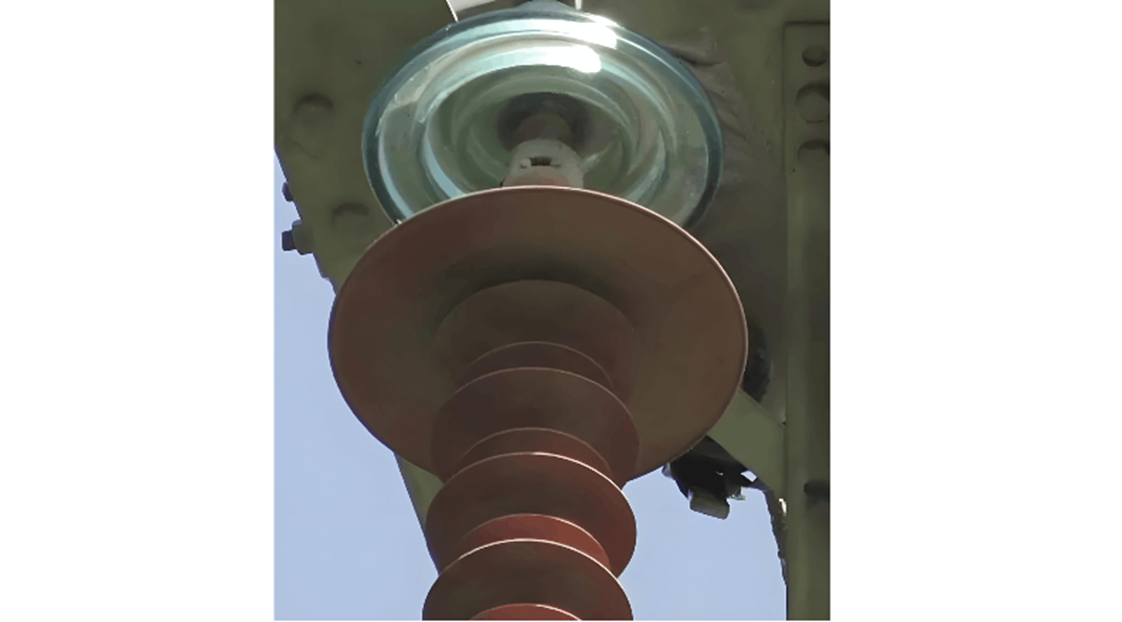
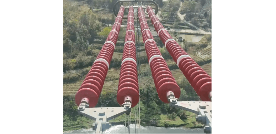
Adjusting Creepage Distance ("Climbing"): Based on specified creepage ratios in pollution zone maps, adjusting the external insulation creepage distance of electrical equipment in that area is called adjusting creepage distance, or "climbing". Methods include adding more insulator discs, replacing with longer creepage distance insulators, or using composite insulators.
Cleaning: A relatively simple method among anti-pollution technical measures involves removing accumulated contaminants from the insulator surface to restore its original insulation level. Cleaning can be done while energized or de-energized, with energized cleaning methods including water flushing, air blowing, and electric brushes.
Surface Treatment: Porcelain and glass insulator surfaces exhibit hydrophilic properties, making it easy for continuous water films to form under humid conditions, facilitating contamination wetting and leakage current paths. Surface treatment involves applying special coatings to insulator surfaces to enhance hydrophobicity, preventing the formation of leakage current paths during electrification.


