• Product
  • Suppliers
  • Manufacturers
  • Solutions
  • Free tools
  • Knowledges
  • Experts
  • Communities
Search


How does a transformer work?

Rockwell
Rockwell
Field: Manufacturing
China

Transformer Operation Principle

A transformer is an electrical device that operates on the principle of electromagnetic induction to transfer electrical energy from one circuit to another. It enables the adjustment of voltage levels within an alternating current (AC) system, either stepping up (increasing) or stepping down (decreasing) voltage while maintaining the same frequency.

Working Principle:

Basic Components
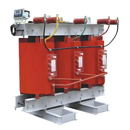
A transformer consists of two coils, known as windings—the "primary winding" connected to the AC power source, and the "secondary winding" connected to the load. These windings are wound around a core typically made of magnetic material (such as iron). The core serves to concentrate and guide the magnetic field generated by the current flowing through the primary winding.

Principle of Electromagnetic Induction
When AC current flows through the primary winding, it produces a continuously changing magnetic field. According to Faraday's Law of Electromagnetic Induction, this changing magnetic field induces a voltage (electromotive force, or EMF) in the secondary winding, even though the two windings are not electrically connected.

Voltage Transformation
The voltage induced in the secondary winding depends on the turns ratio—the ratio of the number of turns in the secondary winding to that in the primary winding. If the secondary has more turns than the primary, the voltage is stepped up; if it has fewer turns, the voltage is stepped down.

Current Transformation
Due to the conservation of power, there is an inverse relationship between voltage and current. When voltage is stepped up, current decreases, and when voltage is stepped down, current increases, thereby maintaining power balance.

Load Connection
The load (such as appliances or machinery) is connected to the secondary winding, which supplies the transformed voltage to power the load.

Isolation and Galvanic Separation
Transformers provide electrical isolation and galvanic separation between the primary and secondary circuits. This means there is no direct electrical connection between the windings, enhancing safety and preventing unwanted current flow between circuits.

In summary, transformers operate on electromagnetic induction, where a changing magnetic field from the primary winding induces a voltage in the secondary winding. By varying the number of turns in the windings, transformers can step up or step down voltage while maintaining power balance between the primary and secondary circuits. Transformers are essential components in power distribution and transmission systems, enabling efficient and safe electricity delivery.

Give a tip and encourage the author!
Recommended
PT Fuse Slow Blow: Causes, Detection & Prevention
I. Fuse Structure and Root Cause AnalysisSlow Fuse Blowing:From the design principle of fuses, when a large fault current passes through the fuse element, due to the metal effect (certain refractory metals become fusible under specific alloy conditions), the fuse first melts at the soldered tin ball. The arc then rapidly vaporizes the entire fuse element. The resulting arc is quickly extinguished by quartz sand.However, due to harsh operating environments, the fuse element may age under the comb
Edwiin
10/24/2025
Why Fuses Blow: Overload, Short Circuit & Surge Causes
Common Causes of Fuse BlowingCommon reasons for fuse blowing include voltage fluctuations, short circuits, lightning strikes during storms, and current overloads. These conditions can easily cause the fuse element to melt.A fuse is an electrical device that interrupts the circuit by melting its fusible element due to heat generated when current exceeds a specified value. It operates on the principle that, after an overcurrent persists for a certain period, the heat produced by the current melts
Echo
10/24/2025
Fuse Maintenance & Replacement: Safety and Best Practices
1. Fuse MaintenanceFuses in service should be regularly inspected. The inspection includes the following items: Load current should be compatible with the rated current of the fuse element. For fuses equipped with a fuse blown indicator, check whether the indicator has actuated. Check the conductors, connection points, and the fuse itself for overheating; ensure connections are tight and making good contact. Inspect the fuse exterior for cracks, contamination, or signs of arcing/discharge. Liste
James
10/24/2025
Maintenance and Repair Items for 10kV High-Voltage Switchgear
I. Routine Maintenance and Inspection(1) Visual Inspection of Switchgear Enclosure No deformation or physical damage to the enclosure. Protective paint coating shows no severe rust, peeling, or flaking. Cabinet is securely installed, clean on the surface, and free of foreign objects. Nameplates and identification labels are neatly affixed and not falling off.(2) Check of Switchgear Operating Parameters Instruments and meters indicate normal values (comparable to typical operating data, with no s
Edwiin
10/24/2025
Related Products
Send inquiry
Download
Get the IEE Business Application
Use the IEE-Business app to find equipment, obtain solutions, connect with experts, and participate in industry collaboration anytime, anywhere—fully supporting the development of your power projects and business.