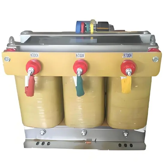
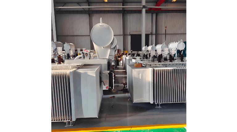
What are the types of power transformers, and what are their main components?
Power transformers are available in various types to meet the evolving demands of power systems. They can be classified as single-phase or three-phase based on phase configuration; core-type or shell-type according to the relative arrangement of windings and core; and dry-type, air-cooled, forced oil circulation air-cooled, or water-cooled based on cooling methods. In terms of neutral point insulation, transformers are categorized as fully insulated or partially insulated. Additionally, insulation classes of windings are designated as A, E, B, F, and H based on material type. Each transformer type has specific operational requirements. The main components of a power transformer include the core, windings, bushings, oil tank, conservator (oil pillow), radiator, and associated accessories.
What is inrush current in transformers, and what causes it?
Inrush current refers to the transient current that flows in transformer windings when voltage is initially applied. It occurs when the residual magnetic flux in the core aligns with the magnetic flux produced by the applied voltage, causing the total flux to exceed the core’s saturation level. This results in a large inrush current, which can reach 6 to 8 times the rated current. The magnitude of the inrush current depends on factors such as the voltage phase angle at energization, the amount of residual flux in the core, and the source system impedance. The peak inrush current typically occurs when the voltage is at zero crossing (corresponding to peak flux). The inrush current contains DC and higher harmonic components and decays over time due to circuit resistance and reactance—typically within 5–10 seconds for large transformers and about 0.2 seconds for smaller units.
What are the methods of voltage regulation in transformers?
There are two primary methods of voltage regulation: on-load tap changing (OLTC) and off-load tap changing (DETC).On-load voltage regulation allows tap position adjustments while the transformer is energized and operating, enabling continuous voltage control by altering the turns ratio. Common configurations include line-end tap and neutral-point tap. The neutral-point tap offers reduced insulation requirements but requires the neutral to be solidly grounded during operation.
Off-load voltage regulation involves changing the tap position only when the transformer is de-energized or during maintenance.
What is a fully insulated transformer, and what is a partially insulated transformer?
A fully insulated transformer (also known as uniformly insulated) has consistent insulation levels throughout the winding. In contrast, a partially insulated transformer (or graded insulation) features reduced insulation levels near the neutral point compared to the line ends.
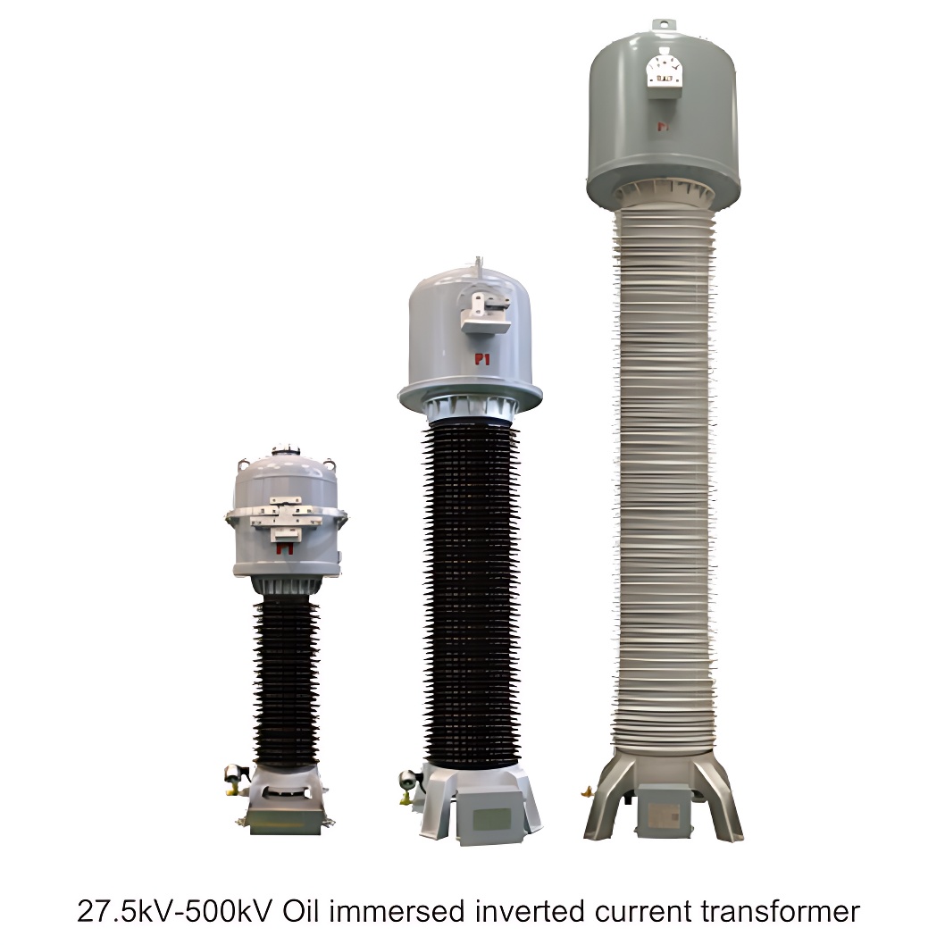
What is the difference in operating principles between voltage transformers and current transformers?
Voltage transformers (VTs) are primarily used for voltage measurement, while current transformers (CTs) are used for current measurement. Key operational differences include:
The secondary side of a CT must never be open-circuited but can be short-circuited. Conversely, the secondary of a VT must never be short-circuited but can be open-circuited.
A VT has very low primary impedance relative to its secondary load, making it behave like a voltage source. In contrast, a CT has high primary impedance and functions as a current source with effectively infinite internal resistance.
Under normal operation, a VT operates with magnetic flux density near saturation, which may decrease during system faults due to voltage drop. A CT, however, operates at low flux density under normal conditions. During short circuits, the increased primary current can drive the core into deep saturation, increasing measurement errors. Therefore, selecting CTs with high saturation resistance is recommended.