Transformer Common Knowledge Q&A

Vziman
08/15/2025

What are the types of power transformers, and what are their main components?

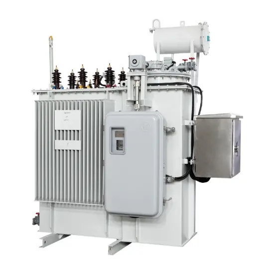
Power transformers are available in various types to meet the evolving demands of power systems. They can be classified as single-phase or three-phase based on phase configuration; core-type or shell-type according to the relative arrangement of windings and core; and dry-type, air-cooled, forced oil circulation air-cooled, or water-cooled based on cooling methods. In terms of neutral point insulation, transformers are categorized as fully insulated or partially insulated. Additionally, insulation classes of windings are designated as A, E, B, F, and H based on material type. Each transformer type has specific operational requirements. The main components of a power transformer include the core, windings, bushings, oil tank, conservator (oil pillow), radiator, and associated accessories.

What is inrush current in transformers, and what causes it?

Inrush current refers to the transient current that flows in transformer windings when voltage is initially applied. It occurs when the residual magnetic flux in the core aligns with the magnetic flux produced by the applied voltage, causing the total flux to exceed the core’s saturation level. This results in a large inrush current, which can reach 6 to 8 times the rated current. The magnitude of the inrush current depends on factors such as the voltage phase angle at energization, the amount of residual flux in the core, and the source system impedance. The peak inrush current typically occurs when the voltage is at zero crossing (corresponding to peak flux). The inrush current contains DC and higher harmonic components and decays over time due to circuit resistance and reactance—typically within 5–10 seconds for large transformers and about 0.2 seconds for smaller units.

What are the methods of voltage regulation in transformers?

There are two primary methods of voltage regulation: on-load tap changing (OLTC) and off-load tap changing (DETC).On-load voltage regulation allows tap position adjustments while the transformer is energized and operating, enabling continuous voltage control by altering the turns ratio. Common configurations include line-end tap and neutral-point tap. The neutral-point tap offers reduced insulation requirements but requires the neutral to be solidly grounded during operation.
Off-load voltage regulation involves changing the tap position only when the transformer is de-energized or during maintenance.

What is a fully insulated transformer, and what is a partially insulated transformer?

A fully insulated transformer (also known as uniformly insulated) has consistent insulation levels throughout the winding. In contrast, a partially insulated transformer (or graded insulation) features reduced insulation levels near the neutral point compared to the line ends.

What is the difference in operating principles between voltage transformers and current transformers?

Voltage transformers (VTs) are primarily used for voltage measurement, while current transformers (CTs) are used for current measurement. Key operational differences include:

  • The secondary side of a CT must never be open-circuited but can be short-circuited. Conversely, the secondary of a VT must never be short-circuited but can be open-circuited.
  • A VT has very low primary impedance relative to its secondary load, making it behave like a voltage source. In contrast, a CT has high primary impedance and functions as a current source with effectively infinite internal resistance.
  • Under normal operation, a VT operates with magnetic flux density near saturation, which may decrease during system faults due to voltage drop. A CT, however, operates at low flux density under normal conditions. During short circuits, the increased primary current can drive the core into deep saturation, increasing measurement errors. Therefore, selecting CTs with high saturation resistance is recommended.
Vziman

Hello! I'm Leon, with 20 years of extensive experience in the power industry. My expertise spans from power distribution equipment to grid operations and maintenance, grounded in robust hands-on and theoretical knowledge. Currently, I focus on sharing insights into electrical equipment fault diagnosis, demystifying complex technical challenges through accessible explanations. I welcome collaboration with industry peers and enthusiasts to collectively explore the intricacies of the power sector.

What is the difference between a dielectric and an insulator?
Dielectrics and insulators are distinguished primarily by their applications. One of the main differences is that a dielectric can store electrical energy by becoming polarized in an electric field, whereas an insulator resists the flow of electrons to prevent current conduction. Other key differences between them are outlined in the comparison chart below.Definition of DielectricA dielectric material is a type of insulator that contains few or no free electrons. When subjected to an electric fi
08/30/2025
Fault Analysis and Treatment of Oil-Immersed Transformers
Oil Leakage at Welded JointsOil leakage at welded joints primarily stems from poor welding quality, such as incomplete or detached welds, and defects like pinholes and gas pores. Although oil-immersed transformers are initially coated with solder and paint during manufacturing, potentially masking these issues temporarily, the defects tend to surface during operation. Additionally, electromagnetic vibration can cause weld cracks, leading to oil leakage.To resolve such leaks, the first critical s
08/29/2025
What losses occur during operation of the transformer? How to reduce losses?
Transformers experience various types of losses during operation, primarily categorized into two main types: copper losses and iron losses.Copper LossesCopper losses, also known as I²R losses, are caused by the electrical resistance of the transformer windings—typically made of copper. As current flows through the windings, energy is dissipated in the form of heat. These losses are proportional to the square of the load current (I²R), meaning they increase significantly with high
Rockwell
08/29/2025
Cable Fault Detection, Testing, Location and Repair
I. Methods for Cable Testing and Inspection:Insulation Resistance Test: Use an insulation resistance tester to measure the insulation resistance value of the cable. A high insulation resistance value indicates good insulation, while a low value may suggest insulation problems requiring further investigation.Voltage Withstand Test: Apply a high-voltage test using a high-voltage tester to verify whether the cable can withstand high voltage under its rated operating conditions. Under normal circums
08/29/2025
Inquiry
Download
IEE-Business is dedicated to serving the personnel in the global power industry.
Join IEE-Business, not only can you discover power equipment and power knowledge, but also canhnd like - minded friends!