Operation and Fault Handling of High and Low Voltage Power Distribution Systems

1 Key Points in Operation of High and Low Voltage Equipment
1.1 High and Low Voltage Equipment
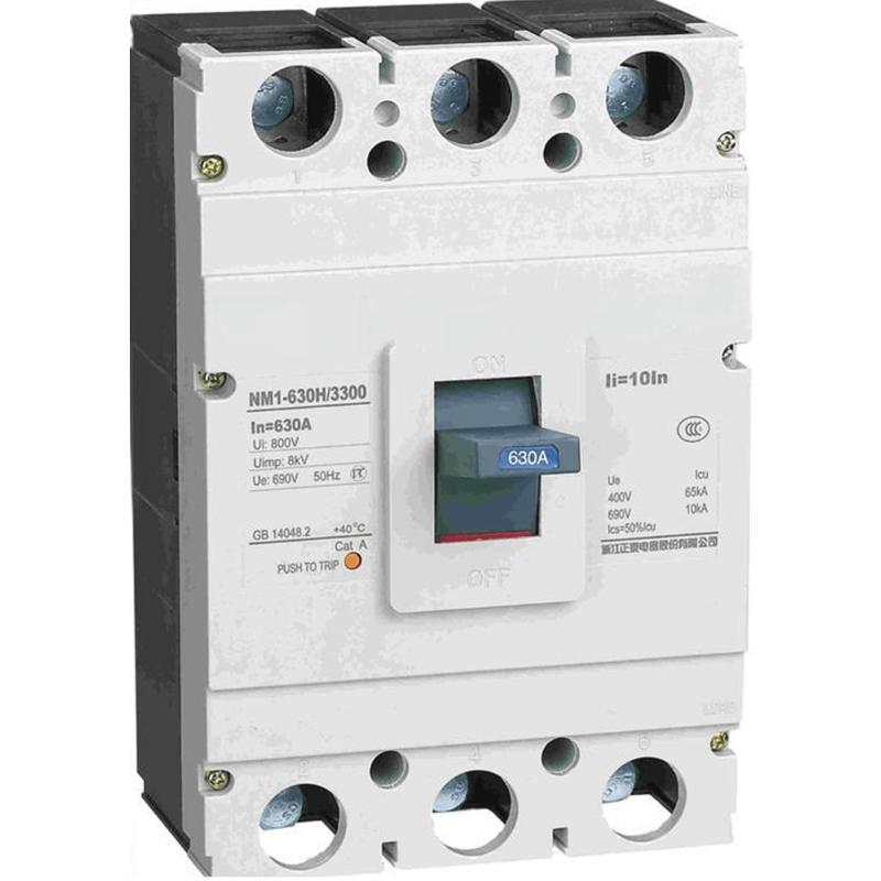
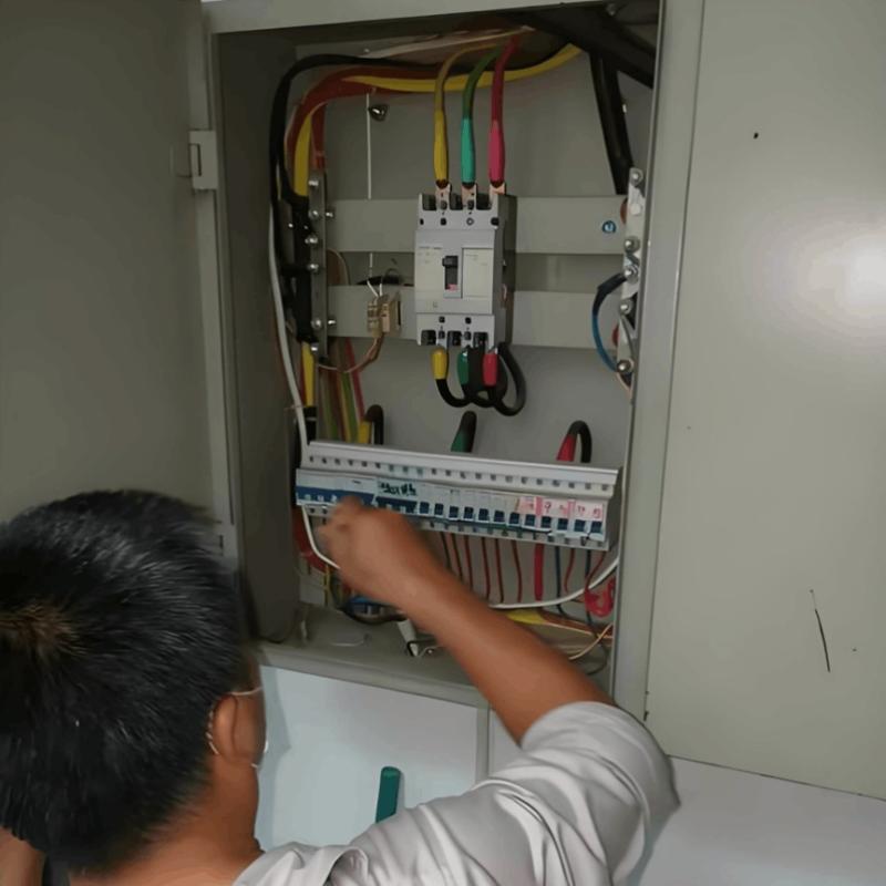
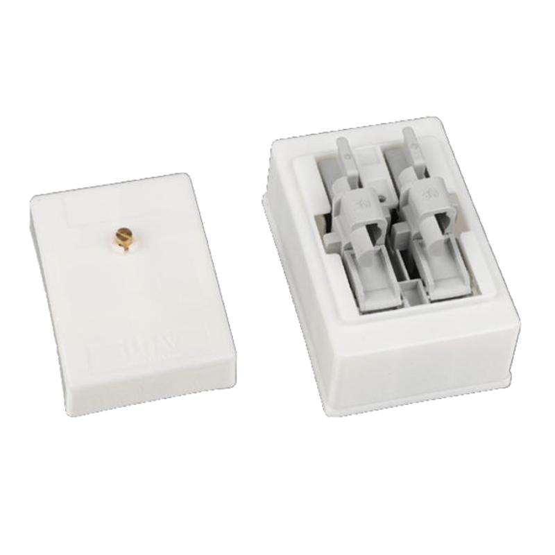
Inspect insulating porcelain components for dirt, damage, or signs of electrical discharge. Check the exterior of low-voltage capacitor compensators for excessive temperature or bulging. If both conditions occur simultaneously, suspend installation work immediately. Examine wiring and terminal joints for oil leakage and conduct a thorough inspection for potential issues.
Use auditory judgment to assess the sound of power transformers during operation. Under normal conditions, a steady "hum" is expected. An abnormally loud hum indicates an overloaded transformer, while sharp or unusual noises suggest high-voltage stress. Monitor oil temperature: it should remain below 85°C and must not exceed 95°C. Excessively high oil temperature may indicate internal faults or equipment overuse.
2 Maintenance of Substation Rooms
2.1 Switching Operations (Switching)
Adjust operational status by taking one or more devices offline or bringing them online based on load requirements. Change power supply modes as per dispatch instructions by switching incoming high-voltage switches. Parallel power transformers and engage busbar switches as needed. Connect power capacitors according to power factor requirements and install surge arresters as specified. Regularly switch backup equipment.
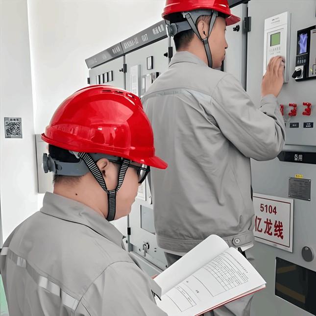
Support production, operations, and maintenance activities through these operations—perform power shutdowns or restorations for shift changes, tasks, or maintenance. Conduct power interruptions or restorations for internal equipment inspections and tests. Implement load shedding during peak usage periods such as holidays. In emergencies, take immediate action to isolate faults. If personnel are at risk, cut power immediately to stop all equipment. Disconnect main power sources in case of natural disasters like fire or flooding.
2.2 Inspections
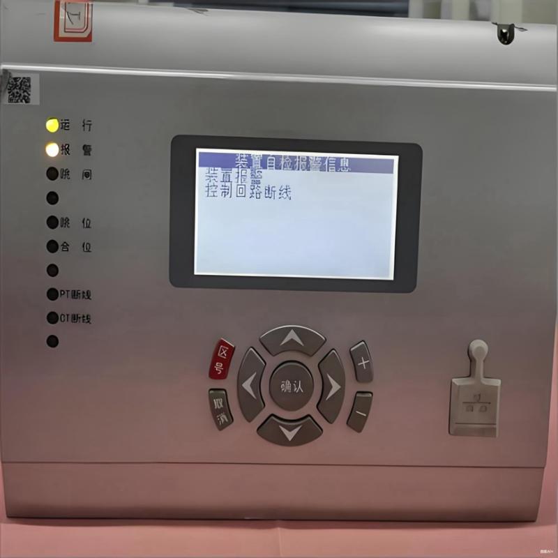
Regular inspections of substations and high/low voltage distribution equipment are essential routine tasks; results should be properly documented. For special or previously faulty equipment, perform additional targeted inspections beyond standard procedures.
2.3 Assisting with Maintenance
Maintenance tasks require coordination among staff. For example, power disconnection before maintenance requires cooperation from designated personnel. During maintenance, safety signage must be posted, which also requires team collaboration.
3 Analysis of Operation and Maintenance for Substations and High/Low Voltage Equipment
3.1 Electromagnetic Operating Mechanism Fails to Close
When an electromagnetic mechanism fails to close, first check if the core is being pulled in. If not, test whether voltage exists at the coil terminals. No voltage may result from loose circuit connections—tighten them and re-measure. Poor contact due to incomplete auxiliary switch transition requires repair to restore normal function. Arc extinguishing chambers may obstruct contactor contacts, or foreign material may block the contactor core—disassemble and reassemble after cleaning. A blown fuse can also cause failure; investigate the cause, eliminate short circuits, select proper fuse elements, and restore circuit functionality. If the electromagnetic coil is broken or burnt out, inspect for open circuits and replace if damaged.
If voltage is present at the coil but the core does not engage, possible causes include a broken or burnt-out closing coil—repair broken leads or replace the coil. Reversed polarity between two coils requires lead adjustment. A stuck closing core may contain debris—disassemble, clean, and reassemble. Mechanical binding can also prevent closure; remove obstructions, resolve jams, and reassemble to restore function.
3.2 Electromagnetic Operating Mechanism Fails to Open
When the mechanism fails to open, determine if the core engages. Measure coil terminal voltage—two scenarios exist: voltage present or absent. No voltage may stem from poor secondary circuit connections or contact issues. Faulty auxiliary switch transition or contact requires repair. A blown fuse should be checked for short circuits; if none exist, replace with a suitable fuse element. If voltage is present but the core does not move, the core may be stuck—disassemble and repair. Remove any foreign objects to ensure smooth operation. Replace the coil if it is broken or burnt. Reverse polarity in dual coils requires correction.
3.3 Electromagnetic Mechanism Closes Then Immediately Releases
This issue may arise from an excessively long reset time of the closing latch support, or deformed end faces—adjust the mechanism and repair the surface. Insufficient depth when the shaft engages the support, indicating improper mechanism adjustment, requires correction to ensure secure engagement. Poor latching of the trip plate should be corrected by securing it properly. Mixed wiring in the secondary circuit may energize the tripping circuit during closing—inspect wiring and correct any errors. Lack of clearance in the closing limit stop screw or excessive pressure from the closing spring buffer without cushioning space requires gap adjustment or spring replacement.
For hydraulic operating mechanisms, the oil pump may fail to build pressure or over-pressurize. Causes include blocked suction lines, clogged oil filters, or restricted oil flow—clear obstructions and flush the system to restore flow. If contamination is severe, clean thoroughly or replace the oil filter. Inadequate air bleeding from the pump requires timely venting. Low oil levels lead to insufficient pressure—refill promptly. Seal leaks require gasket replacement; locate leak points and inspect the pump and motor for damage.
4 Summary
The operation and maintenance of high and low voltage distribution equipment require personnel to continuously accumulate experience and enhance safety and maintenance skills. This ensures reliable equipment operation, minimizes negative factors during operation, and enables systems to meet societal and user demands effectively.