• Product
  • Suppliers
  • Manufacturers
  • Solutions
  • Free tools
  • Knowledges
  • Experts
  • Communities
Search


Operation and Fault Handling of High and Low Voltage Power Distribution Systems

Felix Spark
Felix Spark
Field: Failure and maintenance
China

Basic Composition and Function of Circuit Breaker Failure Protection

Circuit breaker failure protection refers to a protective scheme that operates when the relay protection of a faulty electrical device issues a trip command but the circuit breaker fails to operate. It uses the protection trip signal from the faulty equipment and the current measurement from the failed breaker to determine breaker failure. The protection can then isolate other relevant breakers within the same substation in a short time delay, minimizing the outage area, ensuring overall grid stability, preventing severe damage to generators, transformers, and other faulted components, and avoiding catastrophic grid collapse.

Breaker failure constitutes a dual fault—combining a power system fault with a breaker malfunction. While slightly relaxed performance criteria may be acceptable, the fundamental principle remains: the fault must ultimately be cleared. In modern high-voltage and extra-high-voltage power grids, breaker failure protection is widely adopted as a near-backup protection method.

Composition and Function of Failure Protection

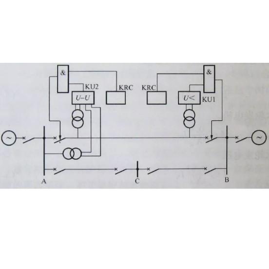
Breaker failure protection consists of a voltage blocking element, a start-up circuit (formed by protection operation and current discrimination), a time-delay element, and a trip output circuit.

The start-up circuit is critical for the correct and reliable operation of the entire protection system. It must be secure and employ dual criteria to prevent false initiation due to single-condition judgment, stuck protection contacts, accidental contact, or unintended energization. The start-up circuit includes two elements forming an "AND" logic:

  • Start Element: Typically uses the breaker’s own automatic trip output circuit. This can be the instantaneous-reset contact of the trip relay itself or a parallel auxiliary intermediate relay with instantaneous return. A contact that has operated but not reset indicates breaker failure.

  • Discrimination Element: Identifies in various ways whether the fault still persists. Existing operational equipment commonly uses “current presence” methods—phase current (for lines) or zero-sequence current (for transformers). If current remains in the circuit after protection operation, it confirms the fault has not been cleared.

The time-delay element serves as an intermediate stage in breaker failure protection. To prevent maloperation caused by a single time-element failure, the time element must form an "AND" logic with the start-up circuit before activating the trip output relay.

The voltage blocking for failure protection generally consists of bus low-voltage, negative-sequence voltage, and zero-sequence voltage relays. When failure protection shares the trip output circuit with bus differential protection, they also share the same voltage blocking elements.

Give a tip and encourage the author!
Recommended
Complete Guide to Circuit Breaker Selection and Setting Calculation
How to Select and Set Circuit Breakers1. Types of Circuit Breakers1.1 Air Circuit Breaker (ACB)Also known as a molded frame or universal circuit breaker, all components are mounted within an insulated metal frame. It is typically open-type, allowing easy replacement of contacts and parts, and can be equipped with various accessories. ACBs are commonly used as main power supply switches. Overcurrent trip units include electromagnetic, electronic, and intelligent types. They provide four-stage pro
Echo
10/28/2025
 Electrical Room Power-On Safety Operation Guide
Electrical Room Power-On Safety Operation Guide
Power Supply Procedure for Low-Voltage Electrical RoomsI. Pre-Power-On Preparations Clean the electrical room thoroughly; remove all debris from switchgear and transformers, and secure all covers. Inspect busbars and cable connections inside transformers and switchgear; ensure all screws are tightened. Live parts must maintain adequate safety clearance from cabinet enclosures and between phases. Test all safety equipment before energizing; use only calibrated measuring instruments. Prepare fire-
Echo
10/28/2025
Operation and Fault Handling of High and Low Voltage Power Distribution Systems
1 Key Points in Operation of High and Low Voltage Equipment1.1 High and Low Voltage EquipmentInspect insulating porcelain components for dirt, damage, or signs of electrical discharge. Check the exterior of low-voltage capacitor compensators for excessive temperature or bulging. If both conditions occur simultaneously, suspend installation work immediately. Examine wiring and terminal joints for oil leakage and conduct a thorough inspection for potential issues.Use auditory judgment to assess th
Felix Spark
10/28/2025
How to improve the operational efficiency and safety of low-voltage distribution networks?
Optimization and Key Considerations for Operation and Maintenance Management of Low-Voltage Distribution NetworksWith the rapid development of China's power industry, operation and maintenance (O&M) management of low-voltage distribution networks has become increasingly important. A low-voltage distribution network refers to the power supply lines between a power transformer and end-user equipment, forming the most fundamental and critical part of the power system. To ensure its normal opera
Encyclopedia
10/28/2025
Related Products
Send inquiry
Download
Get the IEE Business Application
Use the IEE-Business app to find equipment, obtain solutions, connect with experts, and participate in industry collaboration anytime, anywhere—fully supporting the development of your power projects and business.