When dealing with parallel circuits, multiple branches are connected in parallel. Each branch contains components such as resistors, inductors, and capacitors, forming a series circuit within that branch. Each branch is first analyzed separately as a series circuit, and then the effects of all branches are combined.
In circuit calculations, both the magnitude and phase angle of current and voltage are taken into account. When solving the circuit, the magnitudes and phase angles of voltages and currents are considered. There are mainly three methods for solving parallel AC circuits, as follows:
The method that provides a quick result is typically chosen. In this article, the Phasor Method will be explained in detail.
Steps to Solve Parallel Circuits Using the Phasor Method
Consider the following circuit diagram to solve the circuit step - by - step.
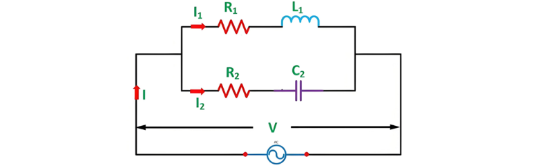
Step 1 – Draw the Circuit Diagram
First, sketch the circuit diagram according to the problem. Take the above circuit as an example, which features two parallel branches:
Step 2 – Calculate Impedance for Each Branch
Determine the impedance of each branch separately:
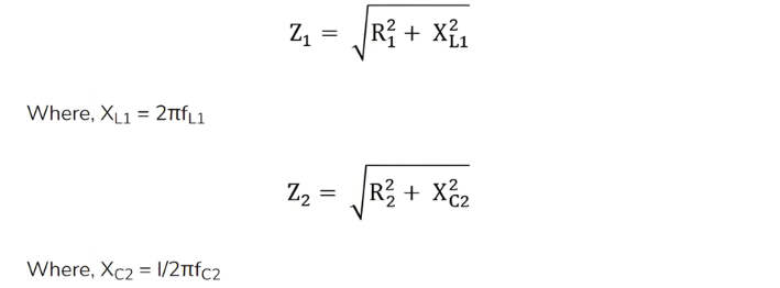
Step 3 – Determine the magnitude of current and phase angle with the voltage in each branch.

Here,
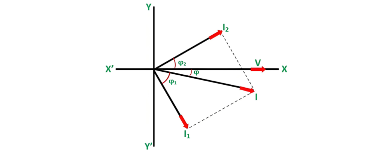
ϕ1 is a lagging angle, indicating an inductive load.
ϕ2 is a leading angle, characteristic of a capacitive load.
Step 4 – Construct the Phasor Diagram
Take the supply voltage as the reference phasor and draw the phasor diagram, plotting the branch currents as shown below:
Step 5 – Compute the Phasor Sum of Branch Currents
Calculate the phasor sum of the branch currents using the component method:

And therefore, current I will be

Step 6 – Find the phase angle ϕ between the total current I and the circuit voltage V.

Here angle ϕ will be lagging as Iyy is negative
The power factor of the circuit will be Cosϕ or

This is all about the phasor method of solving parallel circuits.

 Login