Search


Neutral Point Earthing Modes of Earthing Transformers: Resistor Earthing versus Reactor Earthing

Earthing Transformers

Rockwill
Field: Manufacturing
10Year<
China
Add us on Google

Key Operating Principles

An earthing transformer (commonly Z-connected / zig-zag transformer) merely provides an artificial neutral point for the system. The actual system performance characteristics are governed by the device connected to its neutral terminal.
Neutral Grounding Resistor (NGR) vs Neutral Grounding Reactor (NER)
Item Neutral Grounding Resistor (NGR) Neutral Grounding Reactor (NER)
Grounding Component Resistor R connected in series at neutral point Inductor L connected in series at neutral point
Single-phase Earth Fault Current Limited to tens to hundreds of amperes (value can be precisely set)
 
Controllable
Determined by system capacitive current and reactor compensation degree
 
Difficult to control accurately
Overvoltage Suppression Resistive component dissipates energy, arcs are easy to extinguish
 
Excellent performance in suppressing arc overvoltage
Pure inductive characteristic, compensates capacitive current; resonance overvoltage will occur under detuning condition
 
Risk of resonance
Fault Feeder Selection & Protection Large zero-sequence current, sensitive protection and reliable fault feeder detection
 
Easy to implement
Small residual current, difficult fault feeder identification; dedicated fault detection equipment is required
 
High implementation difficulty
Operation with Persistent Fault Relatively large earth fault current, generally requires rapid fault clearance
 
Short allowable fault duration
Low residual current; short-term earth fault operation is theoretically permitted (arc suppression coil mode)
 
Short-time fault operation supported
Equipment Damage Resistor heats up during faults, design must comply with short-time withstand current
 
Resistor thermal rise needs verification
Low fault current leads to mild thermal stress on equipment
 
Low thermal load
Adjustment Difficulty Fixed resistor type is simple and reliable; additional mechanical structure is required for variable resistors Arc suppression coil needs tap switching according to variation of system capacitive current (automatic tuning)
 
Dynamic tuning is mandatory
Typical Application Scenarios Industrial power distribution (6~35 kV), offshore platforms, mines, data centers, and scenarios requiring fast protection response Urban medium-voltage power grids (large capacitive current), rural overhead lines (continuous power supply required under faults)
National & Industry Standards GB/T 14285, DL/T 620 GB/T 14285, DL/T 620 (for arc suppression coil grounding)

Neutral Point Earthing Modes of Earthing Transformers: Resistor Earthing versus Reactor Earthing

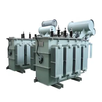
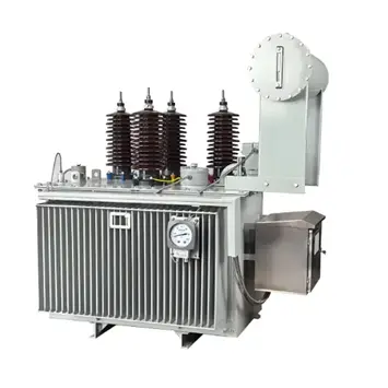
Rockwill 15kV 20kV 22kV 30kV 33kV 35kV oil-immersed neutral grounding resistance to transformer (earthing transfoemer)

Neutral Point Earthing Modes of Earthing Transformers: Resistor Earthing versus Reactor Earthing
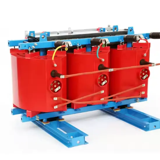
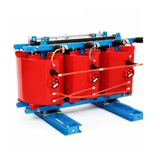
Rockwill Three Phase Cast Resin Dry Type Zigzag (Z-Type) Grounding Transformer 35kV 36kV 44kV 66kV

Resistor Grounding (NGR — Neutral Grounding Resistor)

  • Upon occurrence of a single-phase earth fault, the zero-sequence loop is jointly determined by the system capacitance and the neutral grounding resistor, with the resistor contributing the resistive current component.
  • Arcing ground overvoltage suppression: The resistive current hinders the restriking of the fault arc after current passes through zero crossing, thereby restraining arc restrike.
  • Resistance value selection: Calculated by the formula \(I_R = \dfrac{U_{ph}}{R}\). Generally, \(I_R \ge I_C\) (system capacitive current) is adopted to guarantee sufficient sensitivity of zero-sequence protection.

Reactor Grounding (Arc Suppression Coil Grounding)

  • The inductive current is opposite in phase to the capacitive current; these two currents compensate each other at the fault point, making the residual current close to zero and enabling spontaneous extinction of the fault arc.
  • Compensation degree is defined as \(\delta=\dfrac{I_L-I_C}{I_C}\). Over-compensation (\(\delta>0\)) is the prevailing operation mode to prevent system resonance risks.
  • The residual current still contains active power components caused by line losses as well as higher-order harmonics, so the residual current cannot be reduced to absolute zero.

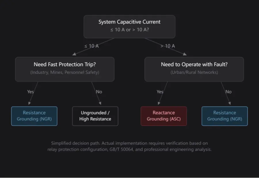
Selection & Decision-Making Logic

iee-business
 

Summary

  Neutral Grounding Resistor (NGR) Reactor Grounding (Arc Suppression Coil)
Core Trade-offs Higher fault current → reliable protection performance, requiring fast fault clearance Low residual fault current → allows continuous operation under faults, yet poses difficulties in faulty feeder identification
Applicable Scenarios Industrial facilities, mines, offshore platforms with safety as the top priority Urban cable power grids & rural overhead line networks with power supply continuity as the primary requirement

Vziman earthing transformers are specially engineered to address the absence of natural neutral points within medium-voltage distribution networks. For systems configured with delta connections or with inaccessible neutral terminals, Vziman products adopt a zig-zag winding topology to artificially establish a stable neutral point. This structure lays the foundational condition for the deployment of arc suppression coil grounding or low-resistance grounding schemes, fundamentally improving the operational safety and power supply reliability of the power grid.

Edited From:Leon

Give a tip and encourage the author!

Comments

Share your question or perspective
WhatsApp
Send inquiry
+86
Click to upload file
Download
Get the IEE Business Application
Use the IEE-Business app to find equipment, obtain solutions, connect with experts, and participate in industry collaboration anytime, anywhere—fully supporting the development of your power projects and business.
Login
or continue with
New here?
Register