After a major overhaul, a 31.5 MVA main transformer was subjected to no-load energization—“Trip!” The differential protection operated—but on-site, there wasn’t the slightest sign of any fault. It wasn’t a fault, yet it resulted in an unplanned power outage:
Why, even though it’s a magnetizing inrush current, does the protection system “fail to recognize” it?
One-sentence conclusion:
The second-harmonic content of the three-phase inrush current is all below the blocking threshold of 15% (with the highest phase at about 10%). As a result, the single “second-harmonic restraint” criterion fails, leading to misidentification of the inrush current as an internal fault. The root cause lies in the combined effect of “high remanent magnetism plus system resonance characteristics,” which significantly depress the harmonic contribution of the inrush current. Additionally, the protection scheme lacks a backup criterion based on waveform symmetry or discontinuity angle.
I. Description of the Incident (Masked)
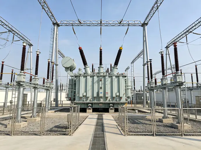
- Scene: A certain 110kV substation—after major overhaul, No. 1 main transformer (31.5 MVA, 110/35/10 kV; indicative parameters) is energized under no-load conditions.
- Phenomenon: At the moment of closing, the main transformer differential protection (ratio differential + second-harmonic restraint) operates, tripping the circuit breakers on all three sides.
- Impact: The substation experienced a brief power outage. After switching to maintenance mode, the secondary reclosure was successful, and no equipment damage occurred. However, the false operation triggered an unplanned primary power outage.
- First reaction: Suspect “closing under internal fault” or “circuit issue.”
II. On-site Evidence (Waveform Characteristics)
| Checklist |
Result |
Judgment |
| Equipment appearance/insulation/gas/oil chromatography |
Normal, no signs of malfunction. |
Exclude genuine internal faults |
| CT Polarity, Wiring, and Operation Testing |
Correct—differential no differential current (before closing) |
Eliminate secondary circuit errors |
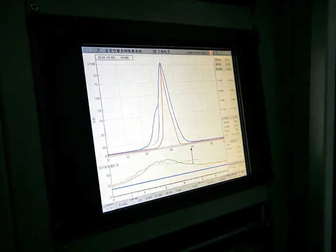
| Recorded waveform of current |
Typical surge waveform: sharp-peak wave, skewed toward one side of the time axis, with signs of discontinuity angles. |
Meets surge characteristics |
| Waveform Second Harmonic Analysis |
The three-phase I₂/I₁ ratios are all below the 15% threshold (with the highest phase at approximately 10%). |
Blocking criterion not met → Differential protection trip → Maloperation |
Why does inrush current occur during no-load closing?
Inrush current exists only on the power supply side (the closing side); there is no current on the other side. Once the differential protection detects inrush current on just one side, a differential current is immediately formed—causing the differential relay to trip without fail. Whether or not the protection can be correctly blocked depends entirely on the criteria used to identify inrush current.
III. Reasoning Chain (From Phenomenon to Root Cause)
- First, check for faults: gas analysis, oil chromatography, appearance, and insulation—all are normal → It’s not a real fault; the inrush current was misidentified.
- Recheck the circuit: CT polarity and operation are both correct → It’s not a circuit error.
- Lockout Criterion Layer: The waveform recorded during the fault clearly shows inrush current—so why didn't the lockout operate? —The lockout criterion is “secondary harmonic content > threshold (15%)”; however, this time, the secondary harmonic ratios I₂/I₁ for all three phases are below the threshold (with the highest phase at around 10%): Physically, it’s an inrush current, but according to the criterion, the lockout conditions aren’t met. (Note: In microprocessor-based protection, the secondary harmonic restraint is phase-specific; each phase is compared independently, and the lockout action applies to the corresponding phase or takes the maximum value among the phases.)
- To further inquire why the second harmonic is so low, let’s consider two factors that overlap: ① Just before the main transformer was closed, it had recently undergone the clearance of a near-zone three-phase fault, leaving high residual magnetization in the core. The closing angle, when superimposed on this residual magnetization, caused the inrush current to become severely skewed, altering the harmonic characteristics and reducing the proportion of the second harmonic. ② The resonant characteristics formed by the parallel capacitor bank within the substation and the system impedance modify the distribution of inrush current harmonics at the sampling point (a shunting effect), thereby further lowering the proportion of the second harmonic. (This factor is controversial within the engineering community and is provided here as an auxiliary explanation.)
- Protection Configuration Vulnerability: This protection scheme relies solely on the "second-harmonic restraint" criterion and does not incorporate the waveform symmetry principle or the discontinuity angle criterion as backup measures. If the single criterion fails, the entire line will lose protection.
IV . Physical root cause (one sentence)
The second-harmonic content of inrush current is suppressed below the blocking threshold by "high remanent magnetism plus system resonance characteristics," while the protection scheme relies solely on a second-harmonic restraint criterion. As a result, the discrimination chain between inrush current and internal faults becomes ineffective.
This reveals a deficiency in the ability to distinguish between redundancy and component failure—any single inrush current characteristic may fail to meet specifications under certain operating conditions. The second-harmonic content of inrush currents in modern high-capacity, low-loss transformers (typically featuring high-permeability silicon steel or amorphous iron cores commonly used in distribution transformers) is generally quite low, and this has become an industry-recognized risk factor.
V. Rectification and Prevention (Three Lines)
1. Protection logic (highest priority)
- The principle of waveform symmetry and the discontinuity angle criterion, combined with second-harmonic restraint, form an "OR" logic—meaning that as long as any one of these criteria is met, differential protection will be blocked (this approach is identical to the method discussed at the 2014 Relay Protection Forum: “Second-Harmonic Restraint + Waveform Symmetry Analysis to Prevent Mis-trips Caused by Inrush Current”).
- Review the second-harmonic restraint ratio (example: 15% → 12%), and simultaneously verify the sensitivity to internal faults (including inrush current components) to prevent false blocking and delay of tripping for actual faults.
- Retain differential fast-trip protection (without inrush current blocking) to ensure reliable and rapid tripping when closing onto an internal fault.
- The transmission test has added a new test item—“Simulated Low Second-Harmonic Inrush Current”—to verify the operating boundaries of the composite criterion.
2. Operating mode
- The main transformer closing is prioritized with the phase-selective closing device (which suppresses inrush current amplitude and harmonic distortion).
- Before closing the switch, assess the impact of the parallel capacitor bank’s operating mode on harmonic sampling distribution (and temporarily disconnect one group if necessary).
3. Management and Archives
- Each time the main transformer is switched on and its waveform data is recorded and filed, a database of inrush current characteristics for that specific main transformer is accumulated, serving as a basis for setting value verification and fault analysis.
- After maintenance, perform the standard demagnetization procedure to reduce the impact of residual magnetism.
- Include "false tripping due to low-second-harmonic inrush current" as a case study in the maintenance team's anti-measure training.
VI. Expert Q&A (FAQ)
Q1: At what level of secondary harmonic content in inrush current will the risk of false tripping be triggered?
It becomes ineffective when the threshold for blocking (indicating 15%) is not met. In engineering practice, it is not uncommon for the three-phase ratio I₂/I₁ to fall below 10%–12% during inrush currents—factors such as large-capacity low-loss cores, high remanence closing, and system resonance characteristics all tend to suppress the harmonic content. Therefore, one should not take "second harmonic > 15%" as an inevitable occurrence.
Q2: Besides second harmonic, what other inrush current discrimination criteria are there?
The four commonly used methods are: ① Second-harmonic restraint; ② Discontinuity angle discrimination (the discontinuity angle of single-phase inrush current typically ranges from 60° to 120°; phase-by-phase discrimination—due to varying closing angles or residual magnetism, the discontinuity angle is usually not obvious in at least one phase for three-phase inrush currents; fault currents, however, show no discontinuity); ③ Symmetry principle of waveforms (inrush currents exhibit asymmetry between the two half-cycles before and after the inrush, whereas fault waveforms are symmetrical); ④ Discrimination based on magnetic flux characteristics (ΔΦ). Modern protection schemes should employ at least a dual criterion or logical combination of “second harmonic + waveform symmetry/discontinuity angle.”
Q3: If you encounter a false trip of the main transformer differential protection on-site, what should you check first?
Follow the sequence: “First rule out actual faults → Then check the circuit wiring → Finally verify the operating criteria”: ① Gas/oil chromatography/insulation/visual inspection confirm no genuine faults; ② Verify CT polarity wiring and perform operational tests; ③ Qualitatively analyze the waveform recording (Is it inrush current? Is it a fault condition?), and re-calculate harmonic content and margin against trip thresholds; ④ Confirm that protection settings match the status of switching devices. The waveform recording serves as the decisive evidence—capture the waveform first, then proceed with any physical actions.
There’s no single “magic bullet” for identifying inrush currents—when operating conditions change, a single criterion can easily become ineffective. A combination of multiple criteria, coupled with feature profiling, is the engineering solution for transformer differential protection.

 Login
Login