In smart medium voltage reclosers such as Rockwill units, the integral CT is commonly specified at 400/1 A. The reason is not that "1 A is more accurate." It is that a 1 A secondary suits a digital controller, reduces the secondary burden, tolerates the long cable runs of pole mounted installations, and compresses the secondary short circuit current into a range where electronic sampling is comfortable.
At the same secondary circuit impedance, the rated burden of a 1 A CT is only 1/25 of that of a 5 A CT, because S = I² × Z. Long distance wiring can therefore use a smaller cable cross section, and protection cores are less likely to saturate prematurely under a heavy burden.
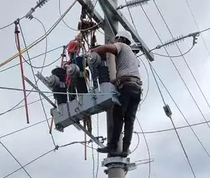
Rockwill recloser pole-mounted site installation
1. What Is a CT Secondary Rating, and How Do 1 A and 5 A Differ?
A current transformer (CT) scales a large primary current down to a standard small secondary current. IEC 61869-2 covers current output CTs, where 1 A and 5 A are the usual rated secondary values; the older Chinese GB system also lists 1 A, 2 A, and 5 A. A ratio of 400/1 A means 1 A on the secondary when the primary carries 400 A, while 400/5 A means 5 A on the secondary at the same primary current.
What is connected downstream decides the choice. Digital recloser controllers and self powered terminals prefer a small current and a light burden; legacy electromagnetic relays and analog meters prefer the larger 5 A signal.
2. Six Advantages of 400/1 A over 400/5 A
2.1 At the same cable impedance the burden falls to 1/25
The CT secondary burden (in VA) is approximately S = I_s² × Z, where I_s is the rated secondary current and Z is the controller input impedance plus the cable loop resistance plus the terminal contact resistance. At the same Z, a 400/1 A CT draws 1²Z = Z VA, while a 400/5 A CT draws 5²Z = 25Z VA.
In other words, a 5 A scheme needs 25 times the burden. The practical result is that 1 A allows a thinner secondary cable and a lower rated VA, and it matches the light burden input of a digital controller far better.
2.2 Cable runs can be far longer
The comparison below assumes equal rated burden and equal copper cross section. The figures are reference values; in practice verify them against the actual cable resistance and controller input.
| Rated burden and secondary |
1 mm² |
1.5 mm² |
2.5 mm² |
4 mm² |
| 2.5 VA, 1 A |
about 69 m |
about 108 m |
about 178 m |
about 277 m |
| 2.5 VA, 5 A |
about 2.8 m |
about 4.3 m |
about 7.1 m |
about 11.1 m |
| 10 VA, 1 A |
about 276 m |
about 432 m |
about 712 m |
about 1108 m |
| 10 VA, 5 A |
about 11.4 m |
about 17 m |
about 28.5 m |
about 44.3 m |
On a pole mounted recloser, the distance from the CT at the pole to the controller below the pole can be tens of metres, so the 1 A advantage is obvious. A 5 A design over the same distance would require either a heavier cable or a higher CT rated burden.
2.3 Less cable drop, so accuracy is easier to hold
Once the total secondary circuit burden exceeds the CT rated burden, ratio error and phase displacement grow. Under fault current, a protection core carrying too much burden may saturate early and exceed its composite error limit.
Because 1 A reduces the VA produced by the same resistance by a factor of 25, the actual burden is much more likely to stay below the rated burden, which leaves a larger accuracy margin. Cable resistance must also be calculated at the maximum operating temperature, not at room temperature.
2.4 Secondary short circuit currents better suited to digital sampling
Rough calculation on the ideal ratio, ignoring saturation and protection class limiting:
| Primary current |
400/1 A secondary |
400/5 A secondary |
| 10 kA |
about 25 A |
about 125 A |
| 16 kA |
about 40 A |
about 200 A |
| 20 kA |
about 50 A |
about 250 A |
At 5 A secondary, a severe fault demands hundreds of amperes from the CT, which places much harder requirements on winding capacity, cable, terminals, sampling resistors, and controller measuring range. The 1 A secondary reduces the fault secondary current by a factor of five, which gives full wave Fourier filtering, harmonic identification, and fault recording considerably more headroom.
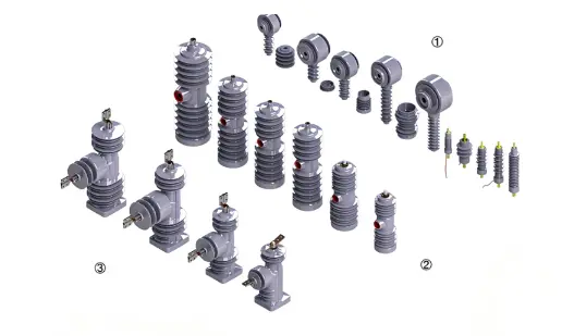
APG epoxy pole with built-in CT
2.5 A better match for self powered and low VA intelligent terminals
A smart recloser can harvest energy from the line CT, with a microprocessor based controller handling overcurrent, earth fault, and reclosing logic independently of an external protection panel. Digital IED current inputs typically draw a fraction of a VA up to a few VA.
A 1 A CT paired with a small rated burden (for example 1.5, 2.5, 3, or 5 VA, depending on the controller manufacturer's data) is more economical than 5 A. Rockwill smart grid automation solutions emphasise grid automation and remote IED monitoring, and such applications favour a small secondary current.
2.6 Small burden increase when several devices are connected in series
Where a measuring core, a protection core, and a feeder automation terminal are fed from the same source, each increment of impedance ΔZ adds burden as follows:
- 1 A: ΔS ≈ 1² × ΔZ = ΔZ
- 5 A: ΔS ≈ 25 × ΔZ
Automation expansion is therefore far more tolerant of burden growth. Even so, keep measuring cores and protection cores separate wherever possible, so that their burdens are not added in series.
One clarification. A 1 A CT is not "safer" simply because its rated value is smaller. An energised CT secondary must never be left open. The induced voltage across an open secondary depends on the ratio, the number of turns, the core, and the protection class, and it cannot be said in general that an open 1 A secondary is more benign. Choosing 1 A is a burden and sampling decision, not a safety decision.
3. When Is 400/5 A Still the Right Choice?
- Existing electromagnetic relays and watt hour meters accept only a 5 A input, and the retrofit will not add auxiliary CTs or signal converters.
- The distance from CT to relay inside the switchgear is very short (for example less than 10 to 20 m), and 5 A drives analog meters and electromagnetic trip coils more directly.
- The whole substation is standardised on 5 A, which simplifies spares, settings, and drawing management.
- Legacy pointer meters and induction watt hour meters are connected directly into the 5 A secondary.
For a new outdoor smart recloser installation, none of these constraints apply, so 400/1 A is the preferred choice.
4. Burden Verification Steps for 400/1 A (for use in technical specifications)
- List the total impedance: controller input impedance + cable loop resistance (out and return length × resistance per unit length, at maximum temperature) + terminal and test block contact resistance (0.05 to 0.1 Ω in total is a reasonable estimate).
- Calculate the actual VA: use S = 1²Z for 400/1 A and S = 25Z for 400/5 A.
- Select a rated VA greater than or equal to the actual VA, with margin. The actual burden is normally kept between 25% and 100% of the rated burden to stay inside the accuracy range.
- For protection cores, verify the ALF. The rated accuracy limit factor is defined at the rated burden. If the actual burden is below rated, the effective ALF rises and the core saturates less readily; if the actual burden is above rated, the effective ALF falls.
- For PX, PS, and similar differential or busbar protection cores, verify against the knee point voltage. The required knee point rises with cable loop resistance, and 1 A can substantially reduce both the required knee point voltage and the core size.
- Reverse select the cable. For long pole mounted runs, first fix 1 A and a small VA, then choose 1.0, 1.5, or 2.5 mm² according to the permitted voltage drop and burden. A 5 A design over the same distance will usually need a heavier cable.
5. Conclusion
Rockwill class smart reclosers use an integral 400/1 A CT rather than 400/5 A for the following main reasons. With a low VA electronic controller input, the rated burden is only 1/25 of the 5 A value, following S = I² × Z. On long pole mounted cable runs the voltage drop is small and a thinner conductor can be used. The actual burden can easily stay below the rated VA, so a protection core is less likely to saturate through excessive burden during a fault. A fault of 10 to 25 kA gives an ideal secondary current of about 25 to 62.5 A, which suits digital sampling and self powered terminals far better than the 125 to 312.5 A of a 5 A scheme. When several IEDs are connected in parallel, the added burden is small. Where compatibility with legacy 5 A relays is required, or where analog panel meters sit close by inside the switchgear, or where the owner mandates 5 A, a 400/5 A version can be supplied to order. For new outdoor automation reclosers, 400/1 A is recommended.

Mass production of Rockwill reclosers
FAQ
Q: Is a 400/1 A CT more accurate than a 400/5 A CT?
A: Not necessarily. Accuracy depends on the accuracy class, the rated burden, the actual burden, and temperature. The advantage of 1 A is that at the same cable resistance it produces a smaller burden, so over a long run the actual burden is easier to hold below the rated VA and accuracy is less likely to be lost. The ratio itself is not inherently more accurate.
Q: For a pole mounted recloser with a 50 m run, should I use 1 A or 5 A?
A: With a digital controller and a small VA input, 1 A is preferred. For the same 2.5 mm² cable and 2.5 VA, a 1 A secondary can theoretically reach well over one hundred metres, while a 5 A secondary reaches only about 7 m. In a 50 m application, a 5 A design would usually need a substantially higher VA or a heavier cable.
Q: Is an open circuit on a 1 A CT safer?
A: It cannot be judged that way. The danger of an open secondary depends on the primary current, the ratio, the number of turns, the core, and the protection class. Whether the secondary is 1 A or 5 A, it must be short circuited while the CT is energised, and an open circuit is never permitted.
Q: Can a substation that is entirely 5 A be converted to a Rockwill 1 A recloser?
A: Yes, but if the downstream relays or meters accept only 5 A, you will need auxiliary CTs, signal converters, or a 5 A version of the recloser. For a new, fully digital system, 1 A is the more economical choice.
Q: Does IEC mandate 1 A or 5 A?
A: No, there is no mandatory choice between the two. IEC 61869-2 covers accuracy, burden, and protection class requirements for current output CTs rated 1 A and 5 A. The choice depends on cable length, downstream equipment, and saturation verification.
Edited From:Garca

 Login
Login