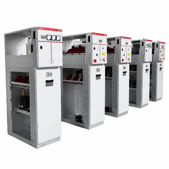
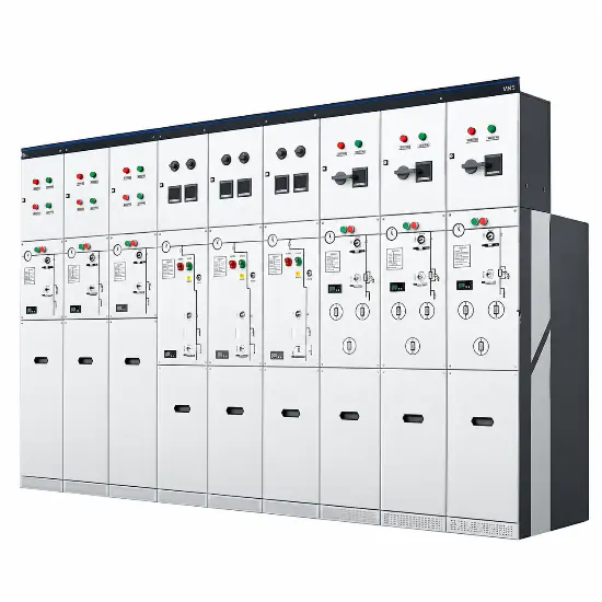
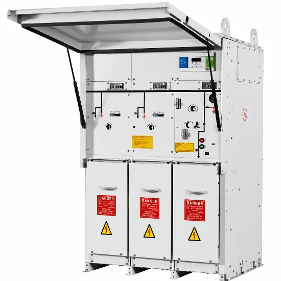
A Ring Main Unit (RMU) is a compact, factory-assembled medium-voltage switchgear unit used in distribution networks. It connects incoming and outgoing medium-voltage cables and provides controlled power supply to a distribution transformer or other feeder.
In simple terms, an RMU performs three main functions:
- Switching — connects or disconnects sections of the medium-voltage network.
- Protection — clears transformer or feeder faults using fuses or circuit breakers.
- Isolation and earthing — separates a faulty section and provides a safe earthed condition for maintenance.
A typical RMU contains:
- Two ring-cable ways
- One or more transformer or feeder ways
- Load-break switches
- Earthing switches
- HRC fuses or vacuum circuit breakers
- Current transformers and protection relays, when required
- Voltage presence indicators
- Cable compartments and interlocking mechanisms
RMUs are generally associated with medium-voltage systems such as 6.6 kV, 10 kV, 11 kV, 20 kV and 33 kV, although the actual rating depends on the project specification.
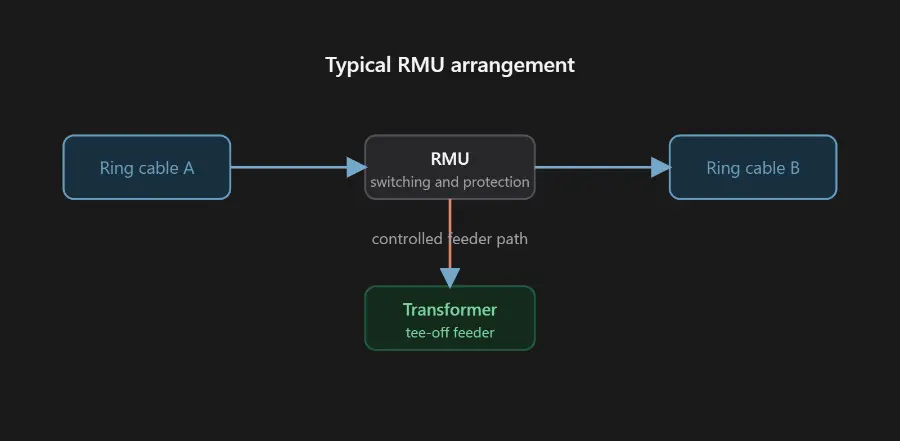
Basic RMU topology
How does an RMU work?
1. Normal power flow
Power enters through one ring cable, passes through the RMU, and leaves through the other ring cable. The tee-off feeder supplies a transformer or local load.
Depending on the utility design:
- Both ring switches may be closed, forming a closed loop.
- One point in the ring may remain normally open to prevent circulating current and simplify protection coordination.
The second arrangement is common in distribution systems because the network can still be supplied from the opposite direction after a fault or maintenance operation.
2. Cable fault isolation
Suppose a fault occurs on one section of the ring cable.
The protection and switching sequence is generally:
- Detect the fault through the protection system.
- Open the appropriate switching devices.
- Isolate the faulty cable section from both sides.
- Keep the healthy network sections energized from the available source.
- Restore supply to unaffected transformers or loads through the alternate path, where the network design permits.
This is the primary reliability advantage of the ring arrangement: a single cable fault does not necessarily interrupt every downstream customer.
3. Transformer fault protection
A transformer feeder may be protected by:
- Fuse-switch combination — common for smaller distribution transformers.
- Vacuum circuit breaker with relay protection — preferred when adjustable protection, remote control, fault recording or more complex coordination is needed.
For a transformer fault, the feeder protection should operate selectively so that the transformer is disconnected without unnecessarily tripping the upstream ring feeders.
4. Earthing and maintenance isolation
An RMU normally includes an earthing switch associated with each cable or feeder way. After the relevant circuit is isolated and verified according to the approved switching procedure, the earthing switch can connect the isolated section to earth.
Mechanical and electrical interlocks are used to prevent unsafe combinations, such as closing an earthing switch onto an energized circuit.
The presence of a voltage indicator is not, by itself, a substitute for an approved isolation, test-before-touch and earthing procedure. Actual switching must be performed only by qualified personnel under the applicable electrical safety rules.
Main types of RMU
1. By insulation technology
| Type |
Main features |
Typical advantages |
Main limitations |
| Air-insulated RMU, AIS |
Conductors and switching devices use air as the primary insulation medium |
Easy visual access, familiar maintenance practices, no sealed gas compartment |
Larger size and greater sensitivity to humidity, dust and pollution |
| Gas-insulated RMU, GIS |
Switching components are enclosed in a sealed gas compartment |
Compact, good environmental resistance, low maintenance |
Gas-handling requirements and environmental considerations |
| Solid-insulated RMU, SIS |
Epoxy or other solid dielectric materials insulate the primary components |
No SF₆ gas, compact design, suitable for harsh environments |
Thermal design, field repair and end-of-life recycling require attention |
| Oil-insulated RMU |
Oil provides insulation and sometimes arc-quenching capability |
Historically used in some systems |
Fire risk, oil ageing and maintenance concerns; less common in modern installations |
Modern projects increasingly evaluate vacuum interruption combined with air, solid or alternative-gas insulation, especially where environmental regulations restrict SF₆ use.
2. By switching and protection function
Load-switch RMU
Uses load-break switches for cable switching and isolation. The transformer feeder may use a separate fuse switch or circuit breaker.
Fuse-protected RMU
Uses a switch-fuse combination on the transformer feeder. It is compact and economical for relatively small transformer ratings.
Circuit-breaker RMU
Uses a vacuum circuit breaker with protection relays. It provides:
- Adjustable overcurrent protection
- Earth-fault protection
- Remote operation
- Better coordination with upstream and downstream equipment
- Fault indication and event recording
Motorized or remotely controlled RMU
Includes motor operators, remote terminal units or communication interfaces. It is used in automated distribution networks and smart-grid applications.
3. By number of ways
Common configurations include:
- 2-way RMU — two ring cable switches
- 3-way RMU — two ring ways plus one transformer feeder
- 4-way RMU — two ring ways plus two outgoing feeders
- Multi-way RMU — used where several transformers, feeders or sectionalizing points are connected
The widely used three-way RMU is often described as:
Ring switch + ring switch + transformer feeder
RMU versus conventional switchgear
An RMU is a type of medium-voltage switchgear, but the terms are not identical.
| Feature |
RMU |
Conventional MV switchgear |
| Main purpose |
Compact ring-network switching and transformer connection |
Flexible protection, metering and feeder control |
| Construction |
Compact, often sealed and factory-assembled |
Usually larger, compartmentalized panels |
| Typical arrangement |
Two ring ways plus one or more tee-off ways |
Incomer, bus section, feeder and metering panels |
| Protection |
Fuse or compact relay-controlled breaker |
Extensive relay, CT, VT and automation options |
| Installation |
Transformer substations, compact substations, urban networks |
Primary substations, industrial plants and large distribution stations |
Key advantages of an RMU
- Improved supply continuity through alternate feeding paths
- Compact footprint
- Reduced installation time
- Integrated switching, protection and earthing
- Better environmental protection in sealed designs
- Suitable for underground cable networks
- Compatible with distribution automation
- Lower maintenance requirements for sealed units
Important selection parameters
When selecting an RMU, engineers should verify at least:
- Rated voltage
- Rated normal current
- Short-time withstand current
- Peak withstand current
- Short-circuit duration
- Power-frequency withstand voltage
- Lightning impulse withstand level
- Internal arc classification
- Insulation medium
- Cable termination type
- Transformer feeder protection method
- Earthing-switch capability
- Environmental and altitude conditions
- Remote-control and communication requirements
- Interlocking and safety provisions
- Applicable utility and national standards
For metal-enclosed medium-voltage switchgear, IEC 62271-200 is a key reference covering AC metal-enclosed switchgear and controlgear above 1 kV and up to and including 52 kV. The exact RMU specification must also consider the relevant switch, circuit-breaker, fuse, protection and local utility requirements. IEC 62271-200 scope reference
Summary
An RMU is the compact switching and protection hub of a medium-voltage ring distribution network. Its two ring ways maintain network continuity, while its tee-off feeder supplies a transformer or local load. During a fault, the RMU isolates only the affected section as far as the protection and network arrangement allow, while healthy sections can remain energized or be restored through an alternate route.
The most important distinction is:
The ring topology provides supply flexibility; the RMU provides the switching, protection and safe isolation needed to operate that topology.
ring main unit supplier,ring main unit manufacturer,ring main unit manufacturer China
Contact us:
Edited From:Dyson

 Login
Login