• Product
  • Suppliers
  • Manufacturers
  • Solutions
  • Free tools
  • Knowledges
  • Experts
  • Communities
Search


What is a Solid-State Transformer? 2025Tech, Structure & Principles Explained

Noah
Noah
Field: Design & Maintenance
Australia

1. What is a Solid-State Transformer (SST)?

1.1 Fundamentals and Limitations of Conventional Transformers

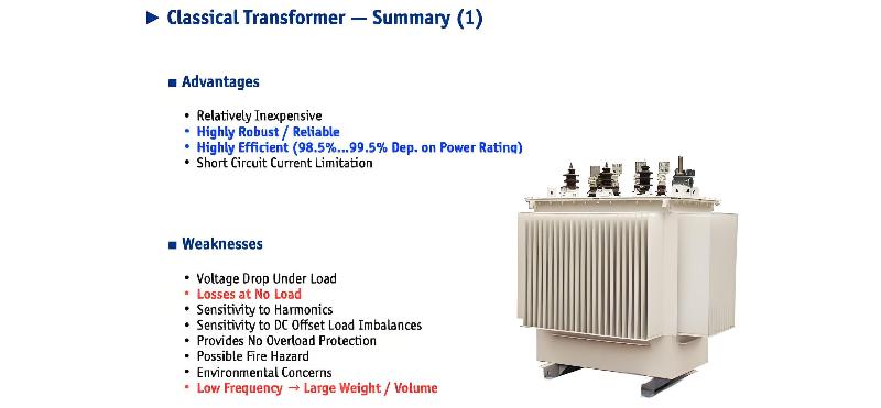
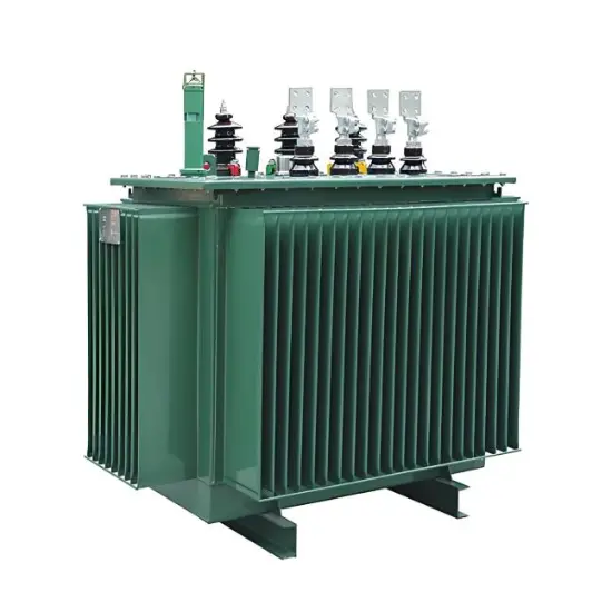
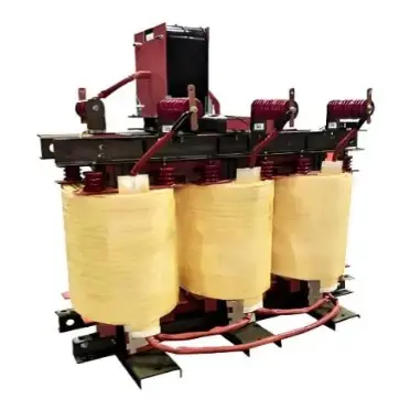
The article first reviews the history (e.g., Stanley's 1886 patent) and basic principles of conventional transformers. Based on electromagnetic induction, traditional transformers consist of silicon steel cores, copper or aluminum windings, and insulation/cooling systems (mineral oil or dry-type). They operate at fixed frequencies (50/60 Hz or 16⅔ Hz), with fixed voltage transformation ratios, power transfer capabilities, and frequency characteristics.

Advantages of conventional transformers:

  • Low cost

  • High reliability (efficiency >99%)

  • Short-circuit current limiting capability

Disadvantages include:

  • Large size and heavy weight

  • Sensitive to harmonics and DC bias

  • No overload protection

  • Fire and environmental risks

1.2 Definition and Origin of Solid-State Transformers

A Solid-State Transformer (SST) is an alternative to conventional transformers based on power electronics technology, with origins tracing back to McMurray's "electronic transformer" concept in 1968. SSTs achieve voltage transformation and galvanic isolation through a Medium-Frequency (MF) isolation stage, while also providing multiple intelligent control functions.

Basic structure of an SST includes:

  • Medium-Voltage (MV) interface

  • Medium-Frequency (MF) isolation stage

  • Communication and control links

SST.jpg

2. Design Challenges of SSTs

2.1 Challenge: Handling Medium Voltage (MV)

Medium-voltage levels (e.g., 10 kV) far exceed the voltage ratings of existing semiconductor devices (Si IGBTs up to 6.5 kV, SiC MOSFETs ~10–15 kV). Therefore, either a multi-cell (modular) or single-cell (high-voltage device) approach must be adopted.

Advantages of multi-cell solutions:

  • Modular and redundant design

  • Multi-level output waveforms, reducing filter requirements

  • Support for hot-swapping and fault tolerance

Advantages of single-cell solutions:

  • Simpler structure

  • Suitable for three-phase systems

2.2 Challenge: Topology Selection

SST topologies can be categorized as:

  • Isolated Front-End (IFE): Isolation before rectification

  • Isolated Back-End (IBE): Rectification before isolation

  • Matrix converter type: Direct AC-AC conversion

  • Modular Multilevel Converter (M2LC)

2.3 Challenge: Reliability

Conventional transformers are extremely reliable, whereas SSTs incorporate numerous semiconductors, control circuits, and cooling systems, making reliability a critical concern. The paper introduces Reliability Block Diagrams (RBD) and failure rate (λ in FIT) models, indicating that redundancy can significantly improve system reliability.

2.4 Challenge: Medium-Frequency Isolated Power Converters

Common topologies include:

  • Dual Active Bridge (DAB): Power flow controlled via phase shift, enabling soft switching

  • Half-Cycle Discontinuous Mode Series Resonant Converter (HC-DCM SRC): Achieves ZCS/ZVS, exhibiting "DC transformer" characteristics

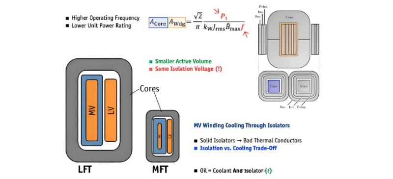
2.5 Challenge: Medium-Frequency Transformer Design

Medium-frequency transformers operate at kHz-level frequencies, facing challenges such as:

  • Smaller magnetic core volume

  • Conflict between insulation and thermal management

  • Uneven current distribution in Litz wire

2.6 Challenge: Isolation Coordination

Medium-voltage units require high insulation to ground, necessitating consideration of:

  • Combined 50 Hz power frequency and medium-frequency electric field stress

  • Dielectric losses and risk of localized overheating

2.7 Challenge: Electromagnetic Interference (EMI)

Common-mode currents generated during MV switching can flow to ground through parasitic capacitance and must be suppressed using common-mode chokes.

2.8 Challenge: Protection

SSTs must handle overvoltage, overcurrent, lightning strikes, and short circuits. Traditional fuses and surge arresters remain applicable but should be combined with electronic current limiting and energy absorption strategies.

SST.jpg

2.9 Challenge: Control

SST control systems are complex and require a hierarchical structure:

  • External control: Grid interaction, power dispatch

  • Internal control: Voltage/current regulation, redundancy management

  • Unit-level control: Modulation and protection

2.10 Challenge: Construction of Modular Converters

Building practical MV modular systems involves:

  • Insulation design

  • Cooling systems

  • Communication and auxiliary power

  • Mechanical structure and hot-swappable support

2.11 Challenge: Testing of MV Converters

MV testing facilities are complex and require:

  • High-voltage, high-power sources/loads

  • High-precision measurement equipment (e.g., high-voltage differential probes)

  • Backup test strategies (e.g., back-to-back testing)

3. Applicability and Use Cases of SSTs

3.1 Grid Applications

SSTs can be used in power grids for:

  • Voltage regulation and reactive power compensation

  • Harmonic filtering and power quality improvement

  • DC interface integration (e.g., energy storage, photovoltaics)

However, compared to conventional Line Frequency Transformers (LFTs), SSTs face an "efficiency challenge":

  • LFT efficiency can reach 98.7%

  • SSTs typically achieve only ~96.3% due to multi-stage conversion

  • Limited reduction in size and weight (~2.6 m³ vs. 3.4 m³)

  • Significantly higher cost (>52.7k USD vs. 11.3k USD)

3.2 Traction Applications

Traction systems (e.g., electric locomotives) have stringent requirements for size, weight, and efficiency, where SSTs offer clear advantages:

  • Significantly reduced transformer size through higher operating frequencies (e.g., 20 kHz)

  • Dual optimization of efficiency and volume reduction

3.3 DC-DC Applications

In DC systems (e.g., offshore wind power collection, data centers), SSTs are the only viable isolation solution, as their operating frequency can be freely chosen without being constrained by grid frequency.

4. Future Concepts and Conclusion

4.1 Future Application Scenarios

  • Subsea oil & gas processing systems

  • Airborne wind turbines

  • All-electric aircraft

  • Naval medium-voltage DC (MVDC) systems

Give a tip and encourage the author!
Recommended
 What Is the Working Principle of a Power Plant Boiler?
What Is the Working Principle of a Power Plant Boiler?
The working principle of a power plant boiler is to utilize the thermal energy released from fuel combustion to heat feedwater, producing a sufficient quantity of superheated steam that meets specified parameters and quality requirements. The amount of steam produced is known as the boiler's evaporation capacity, typically measured in tons per hour (t/h). Steam parameters primarily refer to pressure and temperature, expressed in megapascals (MPa) and degrees Celsius (°C), respectively. Steam qua
Edwiin
10/10/2025
What is the principle of live-line washing for substations?
Why Do Electrical Equipment Need a "Bath"?Due to atmospheric pollution, contaminants accumulate on insulating porcelain insulators and posts. During rain, this can lead to pollution flashover, which in severe cases may cause insulation breakdown, resulting in short circuits or grounding faults. Therefore, the insulating parts of substation equipment must be periodically washed with water to prevent flashover and avoid insulation degradation that could lead to equipment failure.Which Equipment Is
Encyclopedia
10/10/2025
Essential Dry-Type Transformer Maintenance Steps
Routine Maintenance and Care of Dry-Type Power TransformersDue to their flame-resistant and self-extinguishing properties, high mechanical strength, and ability to withstand large short-circuit currents, dry-type transformers are easy to operate and maintain. However, under poor ventilation conditions, their heat dissipation performance is inferior to that of oil-immersed transformers. Therefore, the key focus in the operation and maintenance of dry-type transformers is controlling the temperatu
Noah
10/09/2025
What Causes Boiling or Popping in Transformers
Normal operating sound of a transformer. Although a transformer is static equipment, a slight, continuous "humming" sound can be heard during operation. This sound is an inherent characteristic of operating electrical equipment, commonly known as "noise." A uniform and continuous sound is considered normal; an uneven or intermittent noise is abnormal. Tools such as a stethoscope rod can assist in determining whether the transformer's sound is normal. The causes of this noise are as follows: Vibr
Leon
10/09/2025
Related Products
Seed Inquiry
Download
Get the IEE Business Application
Use the IEE-Business app to find equipment, obtain solutions, connect with experts, and participate in industry collaboration anytime, anywhere—fully supporting the development of your power projects and business.