Key Design Considerations for Manufacturing an Effective Isolation Transformer
An isolation transformer is a type of transformer designed to provide electrical isolation between the primary and secondary windings, ensuring safety and preventing ground faults. To manufacture an efficient and reliable isolation transformer, several key design factors must be considered. Below are these critical design considerations in detail:
1. Insulation Design
Electrical Isolation: The core function of an isolation transformer is to provide electrical isolation, so it is crucial to ensure that the insulation strength between the primary and secondary windings is sufficiently high. The choice of insulating materials is critical; common options include mica, polyester film, and epoxy resin. The thickness of the insulation layer should be determined based on the operating voltage and safety standards to prevent breakdown.
Creepage Distance and Clearance: Creepage distance refers to the shortest path along the surface of the insulator, while clearance is the shortest straight-line distance through the air. Both parameters must meet relevant safety standards (such as IEC 60950 or UL 508) to prevent arcing or flashover.
Dielectric Withstand Test: After manufacturing, isolation transformers typically undergo a dielectric withstand test (Hi-Pot Test) to ensure they can operate stably at the specified working voltage and withstand transient high-voltage impacts.
2. Core Selection
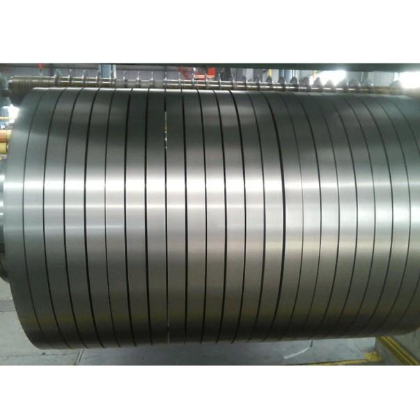
Core Material: The choice of core material significantly affects the efficiency and performance of the transformer. Common core materials include silicon steel, ferrite, and amorphous alloys. Silicon steel offers low losses and high permeability, making it suitable for medium to low-frequency applications; ferrite is ideal for high-frequency applications due to its low eddy current losses; amorphous alloys have extremely low losses, suitable for highly efficient, energy-saving applications.
Core Structure: The structure of the core is also important. Common core structures include EI-type, toroidal, and R-type cores. Toroidal cores offer minimal leakage flux and higher efficiency but are more expensive to manufacture; EI-type cores are easier to produce and less costly but may produce more leakage flux under certain conditions.
Flux Density: Flux density (Bmax) is the maximum magnetic induction level at which the core operates. Excessive flux density can lead to core saturation, increasing losses and reducing efficiency. Therefore, flux density should be designed within the rated range of the core material, based on the operating frequency and power requirements.
3. Winding Design
Turns Ratio: The turns ratio of the isolation transformer determines the voltage ratio between the primary and secondary windings. The turns ratio should be precisely calculated based on the input and output voltage requirements to ensure the transformer provides the necessary voltage conversion.
Winding Arrangement: The arrangement of the primary and secondary windings significantly impacts the transformer's performance. Common winding arrangements include concentric, layered, and dual-winding designs. Concentric windings can reduce leakage flux and improve efficiency; layered windings enhance heat dissipation; dual-winding designs provide better electrical isolation.
Wire Gauge: The wire gauge of the windings should be selected based on the current requirements. Too thin a wire increases resistance and copper losses, while too thick a wire increases material costs and size. The wire gauge should be optimized based on the maximum operating current and temperature rise requirements.
Winding Spacing: The spacing between the primary and secondary windings must be sufficient to ensure electrical isolation. Additionally, winding spacing should consider heat dissipation needs to prevent overheating due to heat accumulation.
4. Temperature Rise and Heat Dissipation Design
Temperature Rise Limitation: Transformers generate heat during operation, primarily due to copper losses (resistive losses) and iron losses (hysteresis and eddy current losses). To ensure long-term reliable operation, the temperature rise must be kept within safe limits. Depending on the application environment and usage conditions, the temperature rise limit is typically between 40°C and 60°C.
Heat Dissipation Design: Effective heat dissipation methods include natural cooling, forced air cooling, or water cooling. For small transformers, natural cooling is often sufficient; for high-power transformers, forced air cooling or water cooling systems may be necessary to ensure good heat dissipation. Proper ventilation design and the use of heat sinks can also help reduce temperature rise.
Insulation Material Temperature Class: The temperature class of the insulating material (e.g., A, E, B, F, H) determines the transformer's performance and lifespan at elevated temperatures. Selecting appropriate temperature-class insulating materials ensures the transformer can operate reliably in high-temperature environments.
5. Electromagnetic Compatibility (EMC) Design
Electromagnetic Interference (EMI) Suppression: Isolation transformers can generate electromagnetic interference (EMI), especially in high-frequency applications. To reduce EMI, filters or shielding can be added to the input and output terminals, or core materials with built-in EMI suppression can be used.
Leakage Flux Control: Leakage flux not only causes energy loss but can also lead to electromagnetic interference with external devices. By optimizing core structure and winding arrangement, leakage flux can be effectively reduced, improving the transformer's EMC performance.
Grounding Design: Proper grounding design can reduce common-mode and differential-mode noise, enhancing the system's electromagnetic compatibility. For isolation transformers, a separate grounding lead is typically provided on the secondary side to ensure electrical isolation while providing good grounding.
6. Safety and Certification
Compliance with International Standards: The design and manufacture of isolation transformers must comply with relevant international standards and regulations, such as IEC 60950, UL 508, and CE. These standards set strict requirements for safety, performance, and reliability, ensuring the product operates safely and reliably in various application environments.
Overload Protection: To prevent damage from overloading, overload protection devices such as fuses, thermal resistors, or temperature sensors are typically installed in the circuit. These devices automatically disconnect the power supply when the current exceeds the safe limit, protecting the transformer from damage.
Short-Circuit Protection: Short circuits are a common fault in transformers and can cause severe damage or even fires. Therefore, isolation transformers should have short-circuit protection, typically achieved using fast-acting fuses or circuit breakers.
7. Efficiency and Power Factor
Improving Efficiency: The efficiency of an isolation transformer depends mainly on copper losses and iron losses. By optimizing core material, winding design, and heat dissipation systems, losses can be minimized, improving transformer efficiency. Efficient transformers not only save energy but also reduce heat generation, extending their lifespan.
Power Factor Correction: In some applications, isolation transformers can cause a drop in power factor, especially with capacitive or inductive loads. To improve the power factor, power factor correction circuits, such as passive or active filters, can be added to the input or output terminals.
8. Size and Weight
Compact Design: In space-constrained applications, the size and weight of the transformer are important considerations. By optimizing core structure, winding design, and heat dissipation systems, the transformer's volume and weight can be reduced while maintaining performance. For example, using toroidal cores or amorphous alloy cores can minimize the transformer's size while ensuring high efficiency.
Modular Design: For applications requiring flexible configuration, a modular design can be adopted, allowing the transformer to be expanded or combined based on different power requirements. Modular design also simplifies production and maintenance, reducing costs.
Summary
Manufacturing an effective isolation transformer requires a comprehensive consideration of multiple key design factors, including insulation design, core selection, winding design, temperature rise and heat dissipation, electromagnetic compatibility, safety, efficiency, and size and weight. By carefully designing and optimizing these aspects, an isolation transformer can achieve efficient, reliable, and safe performance in various application environments.


