How does a power transformer facilitate voltage transformation in electrical systems?

How do Power Transformers Facilitate Voltage Transformation in Electrical Systems?
Power transformers are key devices used in electrical systems to increase or decrease alternating current (AC) voltages. They transform electrical energy from one voltage level to another without changing the frequency, based on the principle of electromagnetic induction. Transformers play a crucial role in power transmission and distribution systems, enhancing transmission efficiency, reducing losses, and ensuring the safe and stable operation of electrical systems.
1. Basic Working Principle of Transformers
Transformers operate based on Faraday's Law of Electromagnetic Induction. Their core structure includes two windings: the primary winding and the secondary winding, both wound around a common iron core. The iron core serves to concentrate and enhance the magnetic field, improving energy transfer efficiency.
Primary Winding: Connected to the power source, it receives the input voltage.
Secondary Winding: Connected to the load, it delivers the output voltage.
When an alternating current flows through the primary winding, it creates a varying magnetic field within the iron core. According to Faraday's law, this varying magnetic field induces an electromotive force (EMF) in the secondary winding, which in turn generates a current. By adjusting the turns ratio between the primary and secondary windings, voltage transformation can be achieved.
2. Principle of Voltage Transformation
The voltage transformation capability of a transformer depends on the turns ratio between the primary and secondary windings. This relationship is described by the voltage ratio formula:

Where:
V1 is the input voltage of the primary winding.
V2 is the output voltage of the secondary winding.
N1 is the number of turns in the primary winding.
N 2 is the number of turns in the secondary winding.
By changing the turns ratio, different voltage transformations can be achieved:
Step-up Transformer: When the number of turns in the secondary winding N2 is greater than that in the primary winding N 1 , the output voltage V2 is higher than the input voltage V1 , i.e., V2 >V1 . Step-up transformers are used to increase low voltage to high voltage, typically in power transmission systems to reduce power losses over long distances.
Step-down Transformer: When the number of turns in the secondary winding N2 is less than that in the primary winding N1 , the output voltage V2 is lower than the input voltage V1, i.e., V2 <V1 . Step-down transformers are used to decrease high voltage to low voltage, typically in distribution systems to convert high-voltage transmission lines to voltages suitable for residential and industrial use.
3. Power Relationship in Transformers
According to the law of conservation of energy, the input power and output power of a transformer are nearly equal (ignoring minor energy losses). The power relationship in a transformer can be expressed as:

Where:
I1 is the input current in the primary winding.
I2 is the output current in the secondary winding.
Since voltage and current are inversely proportional, when the voltage increases, the current decreases, and vice versa. This helps reduce power losses in transmission lines because power losses are proportional to the square of the current (Ploss =I2 ×R). By increasing the voltage, the current is reduced, thereby minimizing losses.
4. Applications of Transformers in Power Systems
Transformers have several key applications in power systems:
Power Plants:In power plants, the voltage generated by turbines is typically low (e.g., 10 kV). To reduce power losses during long-distance transmission, step-up transformers are used to increase the voltage to hundreds of kilovolts (e.g., 500 kV) before transmitting electricity over high-voltage transmission lines.
Transmission Systems:High-voltage transmission lines are used to transport electricity from power plants to various regions. Step-up transformers are widely employed in transmission systems to raise the voltage, reducing current and minimizing line losses.
Substations:Substations serve as critical nodes between transmission and distribution systems. Step-down transformers are used in substations to reduce the high-voltage transmission line voltage to levels suitable for local distribution (e.g., 110 kV, 35 kV, or 10 kV).
Distribution Systems:In distribution systems, step-down transformers further reduce the voltage to levels suitable for residential and industrial use (e.g., 380 V or 220 V). These transformers are typically installed near residential areas or industrial facilities to ensure safe and efficient power delivery.
Special Applications:In specialized applications such as railway traction systems, medical equipment, and communication devices, transformers are used to provide specific voltage and current requirements, ensuring the proper functioning of these devices.
5. Types of Transformers
Depending on different application scenarios and design features, transformers can be classified into several types:
Single-Phase Transformers:Used in single-phase AC systems, commonly found in residential and small commercial power supplies.
Three-Phase Transformers:Used in three-phase AC systems, widely applied in industrial, commercial, and large-scale power transmission systems. Three-phase transformers offer higher power transmission capacity and better efficiency.
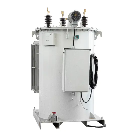
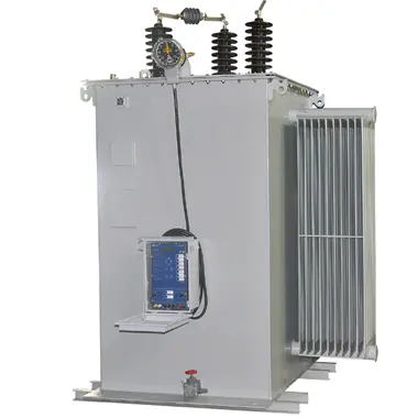
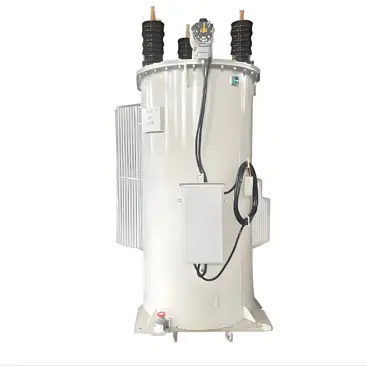
Oil-Immersed Transformers:Use insulating oil as both a cooling medium and an insulating material, suitable for high-capacity and high-voltage applications. Oil-immersed transformers provide excellent heat dissipation and high insulation strength, making them ideal for substations and transmission systems.
Dry-Type Transformers:Do not use liquid cooling media; instead, they rely on natural air cooling or forced air cooling. Dry-type transformers are smaller in size, require less maintenance, and are suitable for indoor installations and environments with strict environmental requirements, such as commercial buildings and hospitals.
Auto-Transformers:The primary and secondary windings share a portion of the same winding, suitable for applications where voltage changes are relatively small. Auto-transformers have a simpler structure and higher efficiency but offer lower safety compared to traditional transformers, often used in specific voltage regulation applications.
6. Advantages of Transformers
High Efficiency:Transformers have very high energy conversion efficiency, typically exceeding 95%. Modern transformers use advanced materials and technologies to further improve efficiency and reduce energy losses.
No Moving Parts:Transformers do not have moving mechanical parts, resulting in high reliability, low maintenance costs, and long service life.
Flexible Voltage Transformation:By adjusting the turns ratio, transformers can flexibly increase or decrease voltage to meet the needs of various applications.
Electrical Isolation:Transformers provide electrical isolation, preventing direct contact between circuits operating at different voltage levels, ensuring system safety and stability.
Reduced Line Losses:By increasing the voltage, transformers significantly reduce the current in transmission lines, thereby minimizing line losses and improving transmission efficiency.
7. Summary
Power transformers facilitate voltage transformation in electrical systems through the principle of electromagnetic induction. They play a vital role in power transmission and distribution, enhancing efficiency, reducing losses, and ensuring the safe and stable operation of electrical systems. Transformers are widely used in power plants, transmission systems, substations, and distribution systems, meeting the diverse voltage and current requirements of different users. Depending on the application, transformers can be classified into single-phase, three-phase, oil-immersed, dry-type, and auto-transformer types, each offering unique advantages and suitable for specific use cases.
Recommended


-
SVR - High Voltage Feed Voltage Regulating Transformer(distribution transformer)

-
6kV 6.35kV 7.62kV 13.2kV 13.8kV 14.4 kV Overhead Line Single Phase Automatic Step Voltage Regulator
-
Voltage stabilization and compensation overhead voltage regulator 6kV 6.35kV 11kV 15kV 22kV 33kV – IEEE for Power Industry
-
Single Phase Automatic Voltage Regulator – 7.62 kV 13.8 kV 14.4 kV 19.92 kV 34.5 kV IEC 60076 compliant for Power Industry