
Circuitus interruptor in vacuo est species circuiti interruptoris in qua medium arcus extinguendi et medium insulans in interstitio inter contactus post extinctionem arcus sunt vacua. Ut unitas protectionis et controlis pro aequipmentis electricis et machinis motoribus in industriis et minis, circuiti interruptores in vacuo alta tensio ad intra habent varia usus et possunt instaurari in armariis fixis, mediolanis, et geminis. Inter claves dispositiva electrotechnica, circuiti interruptores alta tensio conveniunt locis quae requirunt operationes frequentes ad corrente operativa nominata vel interruptiones multiplicis currentis cortocircuiti.
Hoc scriptum analysat problematis commutationis IEE-Business circuiti interruptoris in vacuo non recte aperiendi aut claudi propter operationes frequentes. Per experimenta, invenitur cadere molla tripping ad dexteram cardinis principalem esse causam circuiti interruptoris non recte aperiendi aut claudi. Proponitur melioramentum installationis laminae adjustmentis ut normalis operatio circuiti interruptoris conservetur, quod certum significatum referentiae habet ad constructionem securitatis productionis enterprise.
Structura Circuiti Interruptoris in Vacuo
Circuitus interruptor in vacuo principaliter constat ex componentibus sicut camera arcus extinguendi in vacuo, mechanismus operationis, et supportus.
Camera Arcus Extinguendi in Vacuo
Alias cognita ut tubus commutatoris in vacuo, principium operationis camarae arcus extinguendi in vacuo est ut utilitate excellente insulantis medii vacui intra tubum utatur, faciens ut circuitus mediae et altae tensionis cito extinguant arcum et dissecant currentem postquam supplymentum electricum cessavit. Eius structurae principales sunt:
Systema Insulationis Hermeticum: Hoc est container clausus in ambiente vacuo, principaliter compositus ex cylindro insulationis hermetico, tabula operculi mobilis, tabula operculi fixa, et bellow ex aere inoxido. Ad hermeticitatem conservandam, processus operationis stricti requiruntur pro juncturis sigillandis. Praeterea, materiales cum permeabilitate aeris extremo minus necessarii sunt, et quantitas emissionis gas interioris quoque limitanda est ad minimam valorem.
Systema Conductivum: Principaliter constat ex electrodo fixo et electrodo mobili. Electrodo fixus includit contactum fixum, baculum conductivum fixum, et superficiem arcus cursantis fixam, dum electrodo mobilis includit contactum mobilem, baculum conductivum mobilem, et superficiem arcus cursantis mobilem. Structurae contactuum dividuntur in genera transversalis magneticae cum superficie arcus cursantis spiraligero sulco, longitudinale magneticae, et cylindricae. Mechanismus operationis facit ut duo contactus contineantur per motum baculi conductivi mobilis, ita completur connexio circuiti.
Systema Shielding: Principaliter constat ex cylindro shielding, operculo shielding, et aliis dispositivis. Opercula shielding communiter usitata nunc includunt genera sicut operculum shielding bellows et operculum shielding principale circum contactus. Operculum shielding principale potest reducere fortitudinem localis campi, meliorare uniformitatem distributionis interni campi electrici camarae arcus extinguendi, quod conducit ad miniaturizationem camarae arcus extinguendi in vacuo. Simul prohibet producta arcus splendenti super parietem interior housing insulantis durante processu arcing, asserens ut effectus insulantis housing non afficiatur ab discharge arc. Potest quoque absorbere energiam arcus, condensare producta arcus, et accelerare restitutionem dielectrici fortitudinis in post-arc gap.
Mechanismus Operationis
Diversi genera circuitorum interruptorum utuntur diversis mechanismis operationis. Mechanismi operationis communiter usitati includunt mechanismos operationis spring, mechanismos operationis spring-energy-storage IEE-Business, mechanismos operationis CT8 spring-energy-storage, mechanismos operationis CT19 spring-energy-storage, mechanismos operationis CD10 electromagnetic, mechanismos operationis CD17 electromagnetic, etc. Inter eos, mechanismus operationis spring habet praedicationes magnitudinis parvae, currentis claudendi parvi, et fidei altae, et nunc lata in switchgear diversarum tensionum voltaticarum usus est.
Functio et Principium Circuiti Interruptoris in Vacuo
Functio et Characteristica
Sub conditionibus operationis normalibus, circuitus interruptor in vacuo qui technicis parametris congruit potest suam operationem securam et fidem in rete electrico correspondenti tensio garantire. Vita mechanicus circuiti interruptoris in vacuo est circa 20,000 vices, et numerus interruptionum currentis cortocircuiti plenae capacitatis est 50 vices. Potest frequenter operari vel interruptus currentis cortocircuiti plures vices intra ambitum currentis operativi. Circuiti interruptores alta tensio in vacuo habent praedicationes fidei altae, operationis omnitemporalis, sine maintenance, functionum completarum, bonae interchangeabilitatis, et potentiae generalis forti, et applicari possunt ad operationes reclosing variis characteribus. Circuiti interruptores in vacuo adoptant columnas solidas insulantias verticalis et structuras integrales solid-sealed pole, quae possunt resistere influentia variarum ambientes specialium et sine maintenance. Simul, circuiti interruptores in vacuo habent usus plures, qui possunt instaurari modo fixo, uti modo extractibili, vel instaurari in frame.
Introductio Principii
Cum contactus mobiles et statici circuiti interruptoris in vacuo aperiuntur cum carica, arcus in vacuo generabitur inter contactus. Arcus elevat temperaturam superficiei contactuum, faciens vapor metallicus apparere in superficie contactuum. Ex forma speciali contactuum, cum currente transit, sub actione campi magneticum quod generat, arcus movetur celeriter secundum directionem tangentem superficiei contactuum. Vapor metallicus et particulae chargatae in columna arcus continuo diffunduntur foras, et densitas vaporis metallici et particulae chargatae continue diminuit. Cum arcus naturaliter transeat per zero, medium inter contactus cito restituitur a conductore ad insulator, currentis dissecatur, et arcus extinguitur.
Summa et Analysa Causae Defectus
Analyzando situationem ubi circuitus interruptor in vacuo non aperit aut non aperit complete propter operationes frequentes, inspectio in situ revelat bolt ad dextram cardinis principalem excidere, faciens molla tripping dextera cadere et impingere in cardinem principalem simul. Mechanismus tripping dependet solum a molla tripping sinistra cardinis principalem, resultans in commutatore non aperiendo complete. Etiamsi probabilitas huius defectus occurrentis est comparativus parva, eius occurentia tamen adhuc potest ad accidentia securitatis productionis ducere. Proinde, necesse est analysare causam defectus, eliminare pericula latentes, et securitatem productionis asserere.
Solutio et Planus Verificationis
Screw fixantes molas tripping utriusque lateris cardinis principalem circuiti interruptoris IEE-Business sunt screw ordinarii + washers spring (vide Figura 1). Post annos operationis frequentis commutatoris, screw fixans molla tripping dextera cardinis principalem excidit propter vibrationem, faciens molla tripping dextra cadere et impingere in cardinem principalem simul. Mechanismus tripping dependet solum a molla tripping sinistra cardinis principalem, resultans in commutatore non aperiendo complete. Per investigationem in situ, invenitur differentia longitudinis axialis circa 4mm inter spline shaft dextera cardinis principalem et exterior casing, et operculum deformatum et inflexum intus (vide Figura 2). In responsum ad hunc defectum, id est, defectus circuiti interruptoris causatus a molla tripping excidendo propter solvendum finis bolt closing and opening main shaft, ad verificandum, circuitus interruptor cum structura correspondente reassemblatur pro simulatione defectus:
Ajusta longitudinem axiale inter spline shaft dextera cardinis principalem huius circuiti interruptoris simulati et exterior casing ad creandum hiatus circa 4mm (vide Figura 3), et use torque wrench to tighten it with a torque of 45Nm. Push it into the mechanical running-in chamber for mechanical running-in. The initial counter reading is 26 times, and the end cover shows a slight sunken phenomenon after tightening. The process is shown in Figure 4.
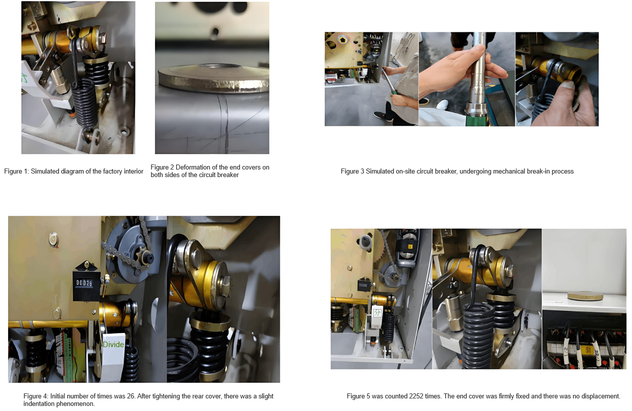
In conclusion, when the specified torque is 45 Nm, even if the axial length between the shaft sleeve and the spline shaft reaches 4 mm and the end cover is deformed and sunken, it remains well-fixed until more than 2,200 operations. Then, it proceeds to the verification of the second stage.
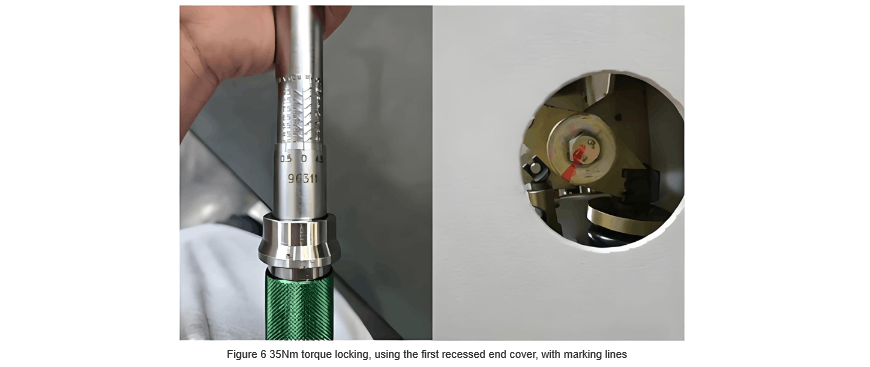
Adjust the axial length between the spline shaft on the right side of the main shaft of this simulated circuit breaker and the outer casing to create a 4-mm gap. Use a torque wrench to tighten it with a torque of 35 Nm, and use the deformed and sunken end cover from stage 1. Mark it with a scribing line. Push it into the mechanical running-in chamber for mechanical running-in. The initial count is 2,252. In summary, when the torque is 35 Nm, even if the axial length between the shaft sleeve and the spline shaft reaches 4 mm and the end cover is deformed and sunken, it remains well-fixed until more than 1,887 operations. Then, it proceeds to the verification of the third stage (see Figure 6).
Adjust the axial length between the spline shaft on the right side of the main shaft of this simulated circuit breaker and the outer casing to create a 4-mm gap. Use a torque wrench to tighten it with a torque of 20 Nm, and use the deformed and sunken end cover from the third stage. Mark it with a scribing line. Push it into the mechanical running-in chamber for mechanical running-in. The initial count is 4,139 (see Figure 7).
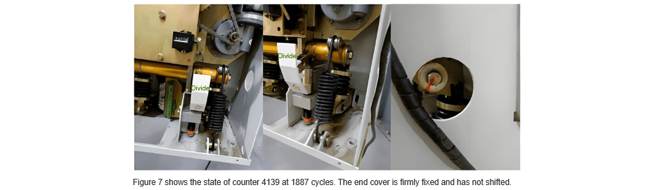
In conclusion, when the torque is 20 Nm, even if the axial length between the shaft sleeve and the spline shaft reaches 4 mm and the end cover is deformed and sunken, it remains well-fixed until more than 1,671 operations. Then, it proceeds to the verification of the fourth stage (see Figure 8 and Figure 9).
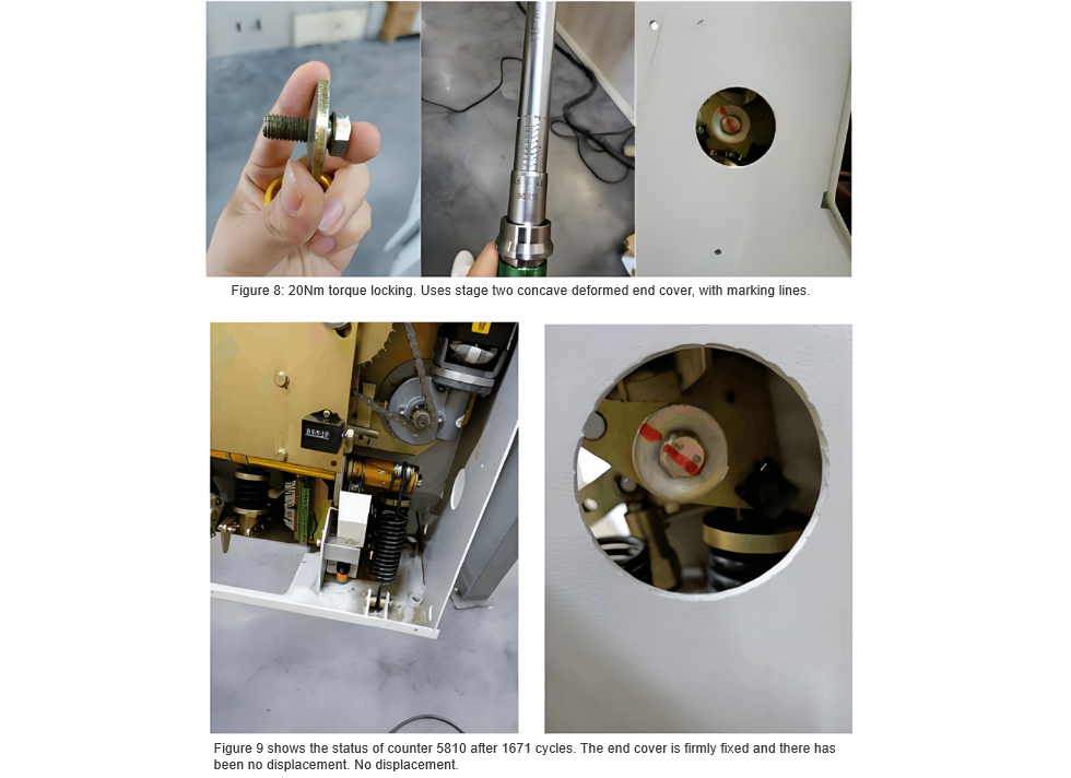
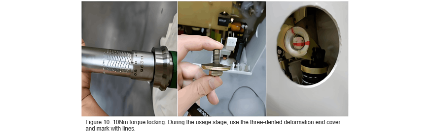
Adjust the axial length between the spline shaft on the right side of the main shaft of this simulated circuit breaker and the outer casing to create a 4-mm gap. Use a torque wrench to tighten it with a torque of 10 Nm, and use the deformed and sunken end cover from the fourth stage. Mark it with a scribing line. Push it into the mechanical running-in chamber for mechanical running-in. The initial count is 5,810 (see Figure 10).
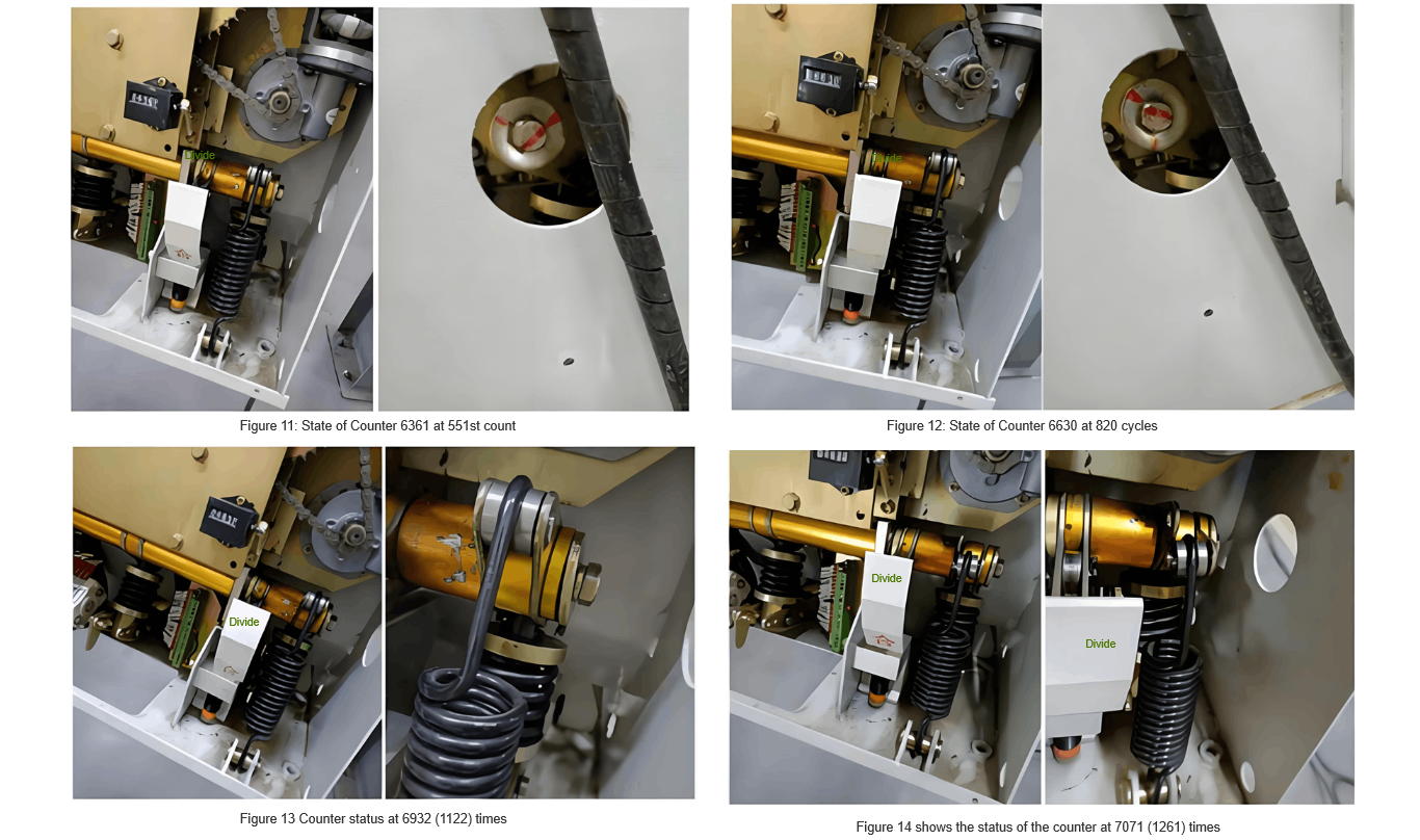
During the test process, it was found that when the counter reached 551 operations, the end cover started to rotate slightly relative to the initial position (see Figure 11); when the count increased to 820 operations, the end cover rotated slightly relative to the position at 551 operations (see Figure 12); when the count reached 1122 operations, the tripping spring was visibly loose to the naked eye (see Figure 13); when the count increased to 1261 operations, the tripping spring fell off (see Figure 14).
Summary of the Test Process
The spindle design of the IEE-Business spring operating mechanism is based on the design of the Belgian IEE-Business company. After the crank arms are accurately positioned, bolts on both sides are tightened to the specified torque value. Spring washers (made of spring steel) are used for anti-loosening via friction. After assembly, the washers are flattened, and their rebound force maintains clamping force and friction between threads. This spindle structure design and anti-loosening measures were proven reliable in mechanical life type tests at the China Electric Power Research Institute (CEPRI).
Early Process Issues of the IEE-Business Mechanism Spindle
In the early assembly process, workers had to adjust sleeves of different tolerance grades to balance dimensions, making assembly quality inconsistent and hard to control. After the circuit breaker spindle was assembled, cumulative errors caused axial length deviations between the internal spline shaft and external sleeve. When bolts were tightened to the specified torque, the middle of the end covers would sag inward. Since the end covers are made of non-spring steel elastic materials, they cannot recover after deformation. Additionally, the spindle sleeve may creep due to impacts during operation, which may gradually reduce the bolt tightening torque (with no obvious changes in fasteners like bolts and end covers until the torque weakens significantly). Conventional maintenance also struggles to apply sufficient torque with ordinary wrenches. Eventually, when the torque drops below 10 Nm, the end covers accelerate loosening, destroying the anti-loosening effect of the spring washers.
Improved Process
To eliminate torque weakening caused by end cover sagging, the process was adjusted: after overall assembly, adjustment shims are uniformly added for balancing. Thread-locking adhesive is applied to bolts, which are then tightened to 45 Nm with a torque wrench. With shims installed, there is no longer space for the end covers to sag inward. The end covers will not gradually reduce the tightening torque due to plastic deformation, ensuring stable and reliable operation of the circuit breaker throughout its service life under sufficient torque.
Rectification Measures
For the circuit breaker with this fault, as shown in Figure 15, install adjustment shims. After aligning the end face of the internal main shaft with the outer sleeve, lock it with bolts. Apply thread-locking adhesive on the bolts and use a torque wrench to tighten them to a torque of 45 Nm.

To prevent the occurrence of such low-probability events, conduct a comprehensive inspection of the circuit breakers that have been put into operation, and install adjustment shims accordingly to ensure that the put-into-operation circuit breakers can work normally and reliably.
Conclusion
This paper focuses on the situation of the high-voltage AC vacuum circuit breaker failing to open properly. By means of simulation analysis and experimental verification, it analyzes the causes of the tripping spring falling off. It is found that the end gasket deforms due to the main shaft gap, and then, after long-term closing and opening vibrations, the tripping spring falls off, resulting in the circuit breaker being unable to open. For this, a solution is proposed, and the feasibility of the solution is demonstrated in detail. Corresponding rectification measures are put forward, so as to eliminate the fault, restore the normal use of the high-voltage vacuum circuit breaker, and ensure the normal production of the enterprise.


