The basic meaning of a high-voltage circuit breaker is, simply put, that under normal conditions, it is used to open (interrupt, trip) and close (make, reclose) circuits, feeders, or specific loads—such as those connected to transformers or capacitor banks. When a fault occurs in the power system, protective relays activate the circuit breaker to interrupt either load current or short-circuit current, thereby ensuring the safe operation of the power system.
A high-voltage circuit breaker is a type of high-voltage switching device—also commonly referred to as a “high-voltage switch”—and is one of the key pieces of equipment in a substation. However, due to the stringent safety requirements of high-voltage substations, personnel generally cannot enter the substation to get close to or physically access these devices. In daily life, one usually only sees high-voltage transmission lines from a distance and rarely gets to observe or touch such switches.
So, what does a high-voltage circuit breaker actually look like? Today, we’ll briefly discuss the common classifications and structural types of circuit breakers. Unlike the low-voltage switches we encounter in everyday life—which typically use only air as the arc-quenching medium—high-voltage circuit breakers demand extremely high performance in terms of insulation and arc interruption, and therefore require special arc-quenching media to ensure electrical safety, insulation integrity, and effective arc extinction. (For more details on insulating media, please refer to our upcoming articles.)
There are two main classification methods for high-voltage circuit breakers:
1. Classification by arc-quenching medium:
(1) Oil Circuit Breakers: Further divided into bulk-oil and minimum-oil types. In both, contacts open and close inside oil, using transformer oil as the arc-quenching medium. Due to limited performance, these types have been largely phased out.
(2) SF₆ or Eco-friendly Gas Circuit Breakers: Use sulfur hexafluoride (SF₆) or other environmentally friendly gases as both insulating and arc-quenching media.
(3) Vacuum Circuit Breakers: Contacts open and close in a vacuum, where arc extinction occurs under vacuum conditions.
(4) Solid-Quench Circuit Breakers: Utilize solid arc-quenching materials that decompose under the high temperature of an arc, producing gas to extinguish the arc.
(5) Compressed-Air Circuit Breakers: Employ high-pressure compressed air to blow out the arc.
(6) Magnetic-Blow Circuit Breakers: Use a magnetic field in air to drive the arc into an arc chute, where it is stretched, cooled, and extinguished.
Nowadays, high-voltage circuit breakers primarily use gases—such as SF₆ or eco-friendly alternatives—as both insulation and arc-quenching media. In the medium-voltage range, vacuum circuit breakers dominate the market. Vacuum technology has even been extended to 66 kV and 110 kV voltage levels, where vacuum circuit breakers have already been developed and deployed.
2. Classification by installation location:
Indoor-type and outdoor-type.
Additionally, based on the insulation method relative to ground, high-voltage circuit breakers can be categorized into three structural types:
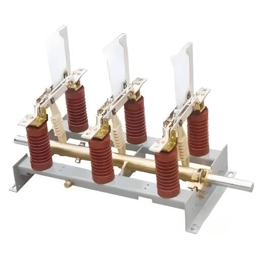
1) Live-Tank Circuit Breaker (LTB):
Also simply called LTB. By definition, this is a circuit breaker in which the interrupter chamber is housed within an enclosure insulated from earth. Structurally, it features a post-type insulator design. The interrupter is at high potential, enclosed within a porcelain or composite insulator, and insulated from ground via support insulators.
Key advantages: Higher voltage ratings can be achieved by connecting multiple interrupter units in series and increasing the height of the support insulators. It is also relatively low-cost.
Equipment based on LTB forms Air-Insulated Switchgear (AIS), and substations built with AIS are known as AIS substations. These offer low investment and simple maintenance but require large land areas and frequent upkeep. They are well-suited for rural or mountainous regions where space is abundant, environmental conditions are favorable, and budgets are limited.

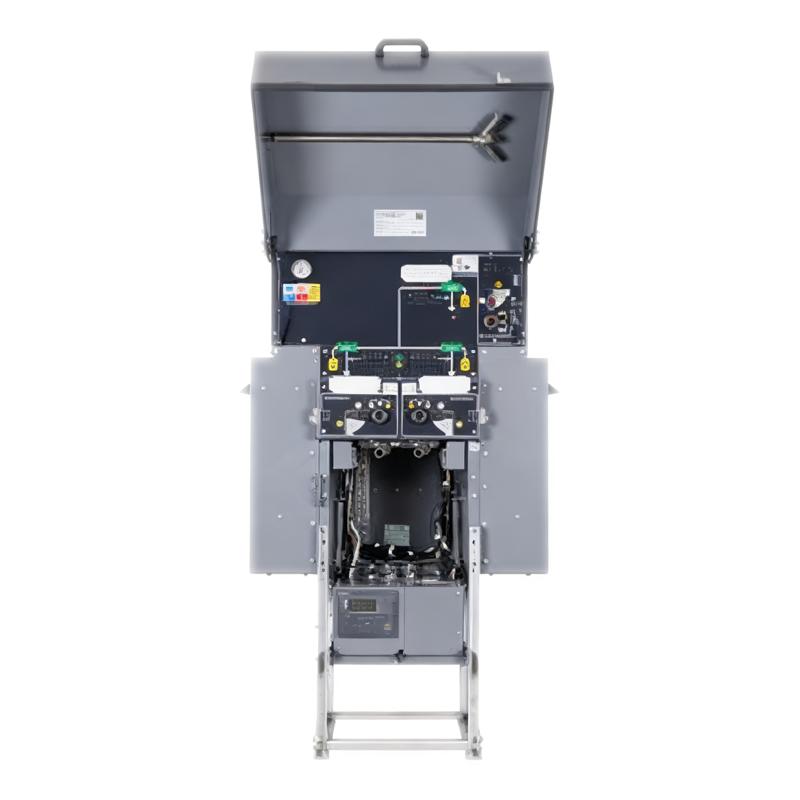
2) Dead-Tank Circuit Breaker (DTB):
Also abbreviated as DTB. Defined as a circuit breaker in which the interrupter chamber is enclosed in a grounded metal tank. The conductive path is led out through bushings.
Crucially, the fundamental difference between LTB and DTB lies in grounding: in DTB, the tank is at earth potential.
Advantages include the ability to integrate current transformers (CTs) directly onto the bushings, compact structure, significantly reduced footprint compared to LTB, better environmental resilience (suitable for harsh conditions), and lower center of gravity—resulting in superior seismic performance. The main drawback is higher cost.
Switchgear based on DTB is known as Hybrid Gas-Insulated Switchgear (HGIS), and the resulting substation is called an HGIS substation.
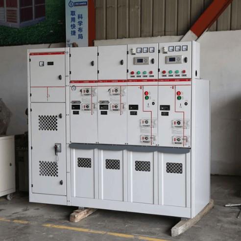
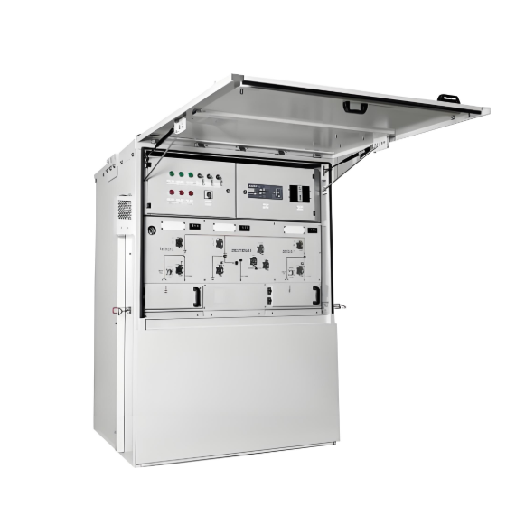
3) Fully Enclosed Combined Structure – Gas-Insulated Metal-Enclosed Switchgear, commonly referred to as GIS (Gas-Insulated Switchgear) in high-voltage applications. This term broadly covers such equipment. The circuit breaker component itself may also be specifically called a GCB (Gas-Insulated Circuit Breaker).
While similar to DTB in that the interrupter is enclosed, GIS differs in that it integrates not just the circuit breaker but also other essential substation components—including disconnectors, earthing switches, instrument transformers, surge arresters, and busbars—all sealed within a grounded metal enclosure filled with pressurized SF₆ (or alternative insulating gas). Connections to external overhead lines are made via bushings or dedicated gas compartments.
Substations built this way are known as GIS substations (or Gas-Insulated Substations per IEEE standards). GIS is ideal for urban areas where land is expensive, or for critical facilities like large hydropower or nuclear plants that demand ultra-high reliability.
By now, the distinctions among high-voltage circuit breaker types—LTB, DTB, GCB—and the corresponding substation configurations—AIS, HGIS, GIS—should be clear.