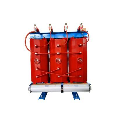
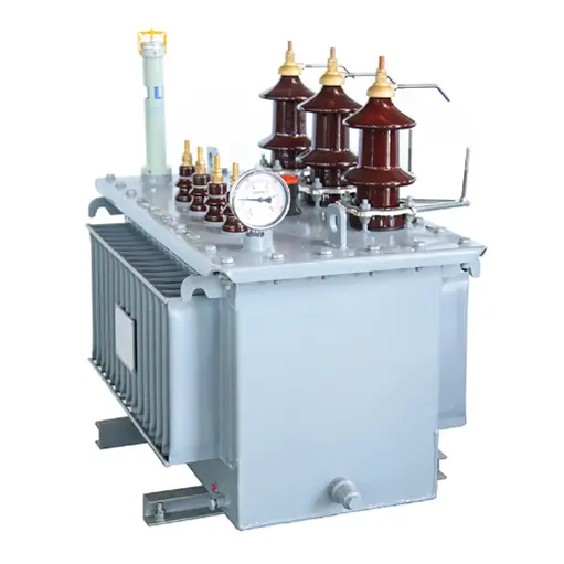
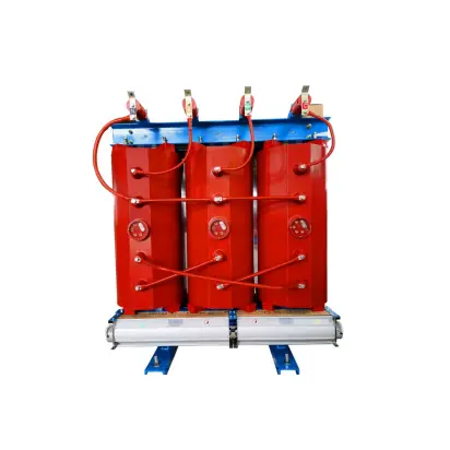
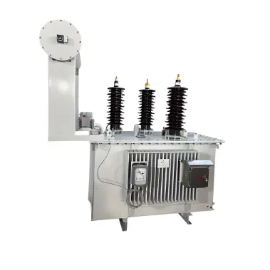
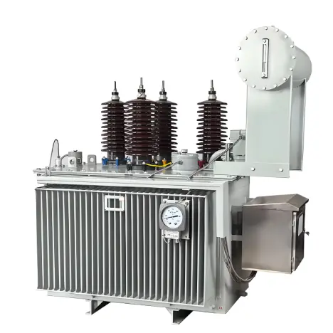
Grounding transformers, commonly referred to as "grounding transformers" or simply "grounding units," operate under no-load conditions during normal grid operation and experience overload during short-circuit faults. Based on the filling medium, they are commonly categorized into oil-immersed and dry-type types; based on phase count, they can be either three-phase or single-phase grounding transformers.
A grounding transformer artificially creates a neutral point for connecting a grounding resistor. When a ground fault occurs in the system, it presents high impedance to positive- and negative-sequence currents but low impedance to zero-sequence current, thereby ensuring reliable operation of ground-fault protection. Proper and rational selection of grounding transformers is of great significance for arc extinction during short circuits, elimination of electromagnetic resonant overvoltages, and ensuring the safe and stable operation of the power grid.
The selection of grounding transformers should be comprehensively evaluated based on the following technical criteria: type, rated capacity, frequency, voltage and current ratings, insulation level, temperature rise coefficient, and overload capability. Environmental conditions must also be carefully considered, including ambient temperature, altitude, temperature variation, pollution severity, seismic intensity, wind speed, and humidity.
When the system neutral point can be directly accessed, a single-phase grounding transformer is preferred; otherwise, a three-phase grounding transformer should be used.

Selection of Grounding Transformer Capacity
The capacity selection of a grounding transformer primarily depends on its type, the characteristics of the equipment connected to the neutral point, and whether there is a secondary-side load. Generally, sufficient margin has already been incorporated into the capacity calculation of the neutral-connected equipment (e.g., arc suppression coil), so no additional derating or safety factor is required during selection.
In photovoltaic power stations, the secondary side of the grounding transformer typically supplies auxiliary loads. Therefore, the author briefly explains how to determine the grounding transformer capacity when a secondary load is present.
Under this condition, the grounding transformer capacity is mainly determined based on the capacity of the arc suppression coil connected to the neutral point and the secondary load capacity. The calculation is performed using a 2-hour rated duration equivalent to the arc suppression coil’s capacity. For critical loads, the capacity may also be determined based on continuous operating time. The arc suppression coil is treated as reactive power (Qₓ), while the secondary load is calculated by separating active power (Pf) and reactive power (Qf). The calculation formula is as follows:

When using ground fault protection based on the reverse-direction active component of zero-sequence current, a grounding resistor of appropriate value is added to either the primary or secondary side of the arc suppression coil to enhance the sensitivity and selectivity accuracy of the ground protection. Although this resistor consumes active power during operation, its usage duration is short and the resulting current increase is small; therefore, no additional capacity increase for the grounding transformer is required.