In medium-voltage distribution networks, and on overhead lines in particular, supply reliability is a core performance indicator. To cope with transient faults such as lightning-induced flashover and tree contact, as well as permanent faults caused by equipment ageing, engineers introduced automated switching devices.
Among them, the recloser and the sectionalizer are the two most fundamental and most important devices, and their coordination forms the classic local-mode Feeder Automation (FA) scheme.
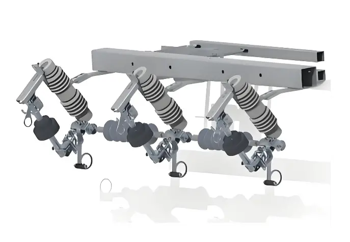
Three‑Phase Mechanical‑Electronic Sectionalizer
1. Core Definitions and Role Positioning
Recloser: a self-protecting intelligent circuit breaker
A recloser is essentially an intelligent circuit breaker with multiple automatic reclosing operations. It integrates the circuit breaker body, protective relaying, the operating mechanism and the control terminal in one unit. It can independently detect fault current, trip, reclose and lock out, and it is capable of interrupting short-circuit fault current (typical interrupting capability 12.5 kA to 25 kA).
Its core value lies in autonomously distinguishing transient faults from permanent faults through a preset trip-close-trip sequence logic. For a transient fault, such as a lightning strike, a successful reclose restores supply. For a permanent fault, after several unsuccessful reclosing attempts the device locks out in the open position and waits for manual reset.
Sectionalizer: an intelligent load-break switch
A sectionalizer is essentially an intelligent load-break switch with a logic memory function. It consists of the load-break switch body, a fault detector relay (FDR) and a control terminal. It is not capable of interrupting short-circuit current, but it can withstand the electrodynamic and thermal stresses of a short circuit, and some models are capable of making (closing onto) short-circuit current.
Its core role is to coordinate with the upstream recloser, opening automatically under loss of voltage or absence of current, so as to precisely isolate the permanent fault section and confine the outage to the smallest possible area.
One-sentence summary of the core difference: the recloser is responsible for breaking fault current, while the sectionalizer is responsible for isolating the fault section.
2. In-depth Comparison: Hardware and Capability Differences
| Characteristic |
Recloser |
Sectionalizer |
| Device nature |
Intelligent circuit breaker |
Intelligent load-break switch |
| Short-circuit current interruption |
Yes (core capability) |
No |
| Short-circuit current making |
Yes |
Some models (make but not break) |
| Withstand short-circuit electrodynamic and thermal stresses |
Yes |
Yes |
| Self-contained protection |
Yes (no external relay required) |
No (depends on upstream coordination) |
| Automatic reclosing |
Programmable sequence |
None |
| Typical installation location |
Substation outgoing feeder, head of the main line |
Branch line entrance, mid-section of long lines |
| Cost reference |
Higher |
About one third to one half of a recloser |
| Applicable standards |
IEC 62271-1, IEC 62271-100, IEEE C37.60 |
IEC 62271-1, IEC 62271-200, IEEE C37.60 |
3. Core Logic: How the Two Devices Work Together
Recloser and sectionalizer coordination follows the principle of time-sequence coordination. The objective is to restore the entire feeder for a transient fault and to isolate only the faulted section for a permanent fault. Two coordination logics are in mainstream use.
Voltage-Time Type Coordination
This is currently the most common mode. The sectionalizer features loss-of-voltage opening and delayed closing on restoration of voltage, governed by two key time settings.
X time (closing delay): the delay from restoration of voltage on the source side of the sectionalizer to automatic closing of that sectionalizer, typically 7 s to 45 s (commonly set in steps such as 7 s, 14 s).
Y time (fault detection time): if voltage is lost again within the Y time after the sectionalizer closes, the section is judged to contain a permanent fault; the sectionalizer opens and blocks its closing function, typically 3 s to 10 s (commonly 5 s).
Operating sequence for a permanent fault:
- Fault occurs→ recloser trips → voltage is lost across the whole feeder → all sectionalizers open automatically and reset.
- First reclosing of the recloser (delay approx. 15 s) → sectionalizers close in sequence according to their X times.
- After the sectionalizer upstream of the faulted section closes, voltage is lost again within the Y time → that sectionalizer identifies the faulted section, opens and blocks.
- After the recloser trips again, it recloses a second time (delay approx. 5 s)→ sectionalizers in the healthy sections close in sequence and restore supply; the faulted section remains open because it is blocked, so isolation is achieved.
Overcurrent Pulse Counting Type Coordination
The sectionalizer counts the short-circuit current pulses passing through it, and when the preset threshold is reached, it opens and blocks during a no-current period.
Key setting rule: the memory time of the sectionalizer must be longer than the Total Accumulated Time (TAT) required by the upstream recloser to complete its full reclosing sequence. If the memory time is too short, the sectionalizer may reset before the recloser completes its sequence, and coordination will fail.
Operating sequence for a permanent fault (counting threshold = 2):
- Fault occurs→ recloser trips →sectionalizer count +1.
- First reclosing of the recloser → fault still present→recloser trips again → sectionalizer count +1 (threshold reached).
- During the no-current window after the second trip, the sectionalizer opens automatically and blocks.
- Second reclosing of the recloser→healthy sections are restored and the faulted section is isolated.
Note: the counting threshold of the sectionalizer must always be lower than the number of operations before the recloser locks out. For example, if the recloser locks out after 4 operations, set the sectionalizer to 2 or 3.
4. Typical Setting Parameter Reference
| Parameter |
Typical value |
Remarks |
| Recloser operating sequence |
One fast two slow, or two fast two slow |
Fast operations for transient faults; slow operations for coordination with downstream devices |
| Recloser fast trip time |
0.05 s to 0.1 s |
Instantaneous, no intentional delay |
| Recloser slow trip time |
0.3 s to 1.0 s |
Time-delayed operation, allowing coordination with downstream devices |
| First reclosing interval |
0.5 s to 5 s (typically 15 s) |
Short delay, used to restore supply after a transient fault |
| Second reclosing interval |
5 s to 30 s (typically 5 s) |
Longer delay, favourable for arc deionization |
| Sectionalizer X time |
7 s to 45 s |
Set in steps according to the number of sections |
| Sectionalizer Y time |
3 s to 10 s (typically 5 s) |
Fault detection window |
| Sectionalizer counting threshold |
2 to 3 |
Must be lower than the recloser lockout count |
| Sectionalizer memory time |
15 s to 30 s |
Must be longer than the recloser TAT |
5. Why Not Use Reclosers Alone Along the Whole Feeder?
- Cost: A sectionalizer costs about one third to one half of a recloser. On long rural feeders or lines with many branches, using sectionalizers for sectional isolation is considerably more economical.
- Reduced outage area: If reclosers alone are used along the whole feeder, a branch fault will trip the main line. Through recloser and sectionalizer coordination, faults can be located and isolated precisely, and healthy areas remain unaffected.
- Simplified O&M: A sectionalizer has a simple structure (load-break switch plus controller), and its O&M cost is far lower than that of a recloser (circuit breaker plus complex control).
6. Emerging Challenge: the Impact of Distributed Energy Resources (DER)
As the penetration of distributed energy resources such as rooftop photovoltaic and wind power increases in overseas distribution networks, conventional voltage-time type FA faces new challenges.
- Reverse power flow may cause a sectionalizer to misjudge the fault direction or to fail in voltage-loss detection.
- Bidirectional fault current may disturb the logic of counting-type sectionalizers.
For networks with high DER penetration, it is recommended to adopt adaptive sectionalizers, which combine voltage-time logic with directional fault detection, or to migrate to a centralized FA scheme based on Feeder Terminal Unit (FTU) communication.
Edited From: Garca

 Login
Login