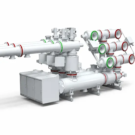
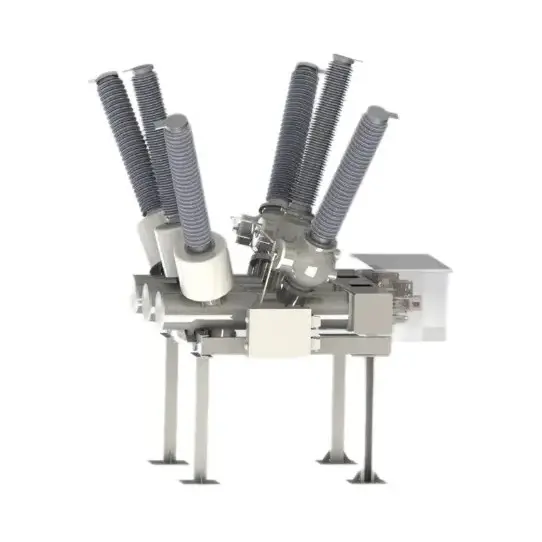
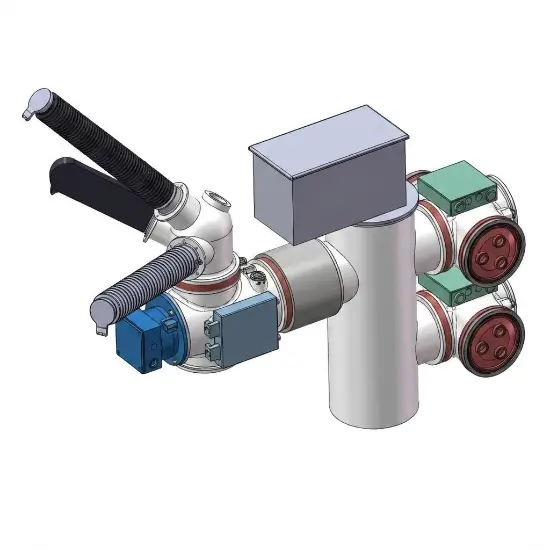
In the 72.5–145kV voltage range, gas-insulated metal-enclosed switchgear (GIS) with a three-phase common enclosure design — where phases A, B, and C conductors are enclosed within a single metal housing and share SF₆ or eco-friendly insulating gas — has become the mainstream configuration. Compared to the three-phase separate enclosure design (each phase in its own housing), the common enclosure design offers the following core advantages:
1. Compact Structure with Significantly Reduced Footprint
Integrating three-phase conductors into a single metal enclosure drastically reduces overall GIS dimensions. For the 72.5–145kV range (commonly corresponding to 110kV power grids), which is frequently used in urban centers, underground substations, or space-constrained areas, the three-phase common enclosure design maximizes space savings in both footprint and height, effectively reducing costly land and civil works expenditures.
2. Magnetic Field Cancellation and Reduced Eddy Current Losses
-
Lower Heat Generation: In the three-phase common enclosure design, conductors are arranged compactly and symmetrically. The resultant magnetic field partially cancels out, resulting in significantly lower eddy current losses on the enclosure compared to the separate enclosure design.
-
Optimized Material Selection: The reduced eddy current losses allow greater flexibility in enclosure material selection. Mainstream designs commonly adopt aluminum alloy enclosures (or low-magnetic stainless steel), which avoid the hysteresis and eddy current heating issues associated with carbon steel, while achieving lightweight construction and long service life. In contrast, three-phase separate enclosure designs must use expensive anti-magnetic materials for each phase enclosure to withstand the strong magnetic field generated by single-phase high currents, resulting in higher material costs and structural weight.
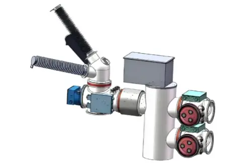
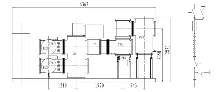
Schematic Diagram of Rockwill RHG-145 Gas-Insulated Metal-Enclosed Switchgear
3. Reduced Sealing Surfaces for Lower Leakage Rates
SF₆ gas leakage typically occurs at flange connections and dynamic seals. The three-phase common enclosure design reduces the number of enclosures, flanges, disc insulators, and sealing rings by approximately two-thirds compared to the separate enclosure design. This significant reduction in sealing surfaces directly lowers leakage risk, enabling extremely low annual gas leakage rates and enhancing long-term sealing reliability.
4. Conservation of Insulating Gas and Materials
Although the common enclosure has a larger diameter than a single separate enclosure, its overall volumetric efficiency is higher. This not only reduces total metal enclosure material weight but also significantly decreases the total filling volume of expensive and high-GWP SF₆ gas (or eco-friendly alternatives), aligning with low-carbon and environmental sustainability trends.
RHD-145 Primary Schematic Diagram for Double Busbar Cable Inlet/Outlet Bay
5. Simplified Mechanical Linkage and Improved Three-Phase Synchronization
The three-phase common enclosure design allows for more compact arrangement of moving contacts for circuit breakers, disconnectors, and earthing switches.
-
This enables all three phases to share a single operating mechanism (e.g., spring or motor mechanism), achieving three-phase synchronized operation through simple internal mechanical linkages.
-
The reduction in transmission components and independent operating mechanisms not only lowers mechanical failure rates but also inherently ensures excellent three-phase closing/opening simultaneity.
6. Easier Installation and Maintenance
-
Transportation and Assembly: The overall weight is lighter, and multiple bays or even entire substation assemblies can be factory-assembled and tested before transport. Only minimal on-site interface work is required, significantly shortening installation schedules.
-
Simplified Maintenance: The number of external support structures, gas pipelines, and density monitor points is greatly reduced, decreasing routine inspection and maintenance workloads.
Conclusion
For the 72.5–145kV voltage range, where insulation distance requirements remain manageable, the three-phase common enclosure design achieves an optimal balance of economy, compactness, low losses, and high reliability. This explains why almost all mainstream switchgear manufacturers worldwide have adopted this design for their 145kV and below GIS products.
Rockwill GIS RHG-145 exemplifies this design philosophy. Featuring a three-phase common enclosure with a bay width of only 0.8 meters, it significantly reduces substation footprints. Equipped with a CT26 spring operating mechanism and self-blast arc-quenching technology, it offers a rated short-time withstand current of 40kA, combining excellent electrical performance with operational reliability. The aluminum alloy enclosure effectively eliminates eddy current losses, offers strong corrosion resistance, and adapts to various harsh environments. Both intelligent and conventional configurations are available, flexibly meeting diverse grid construction requirements.
Edited From:Garca

 Login
Login