
1 Kirki na Superconducting Fault Current Limiter
1.1 Tashar da Addinin Kirkin Superconducting SFCL
Takarda 1 yana takaice da takardun kirkunan kirki na superconducting, wanda ya haɗa da diodis D₁ zuwa D₄, sursu V_b, da kuma karfin L. Wani circuit breaker CB an yi nasara da limiter don koyar da koyar fault current ba da shi a lokacin da an yi gaba. Sursun V_b ya bayyana bias current i_b zuwa karfin L. Amfani V_b ana da ita mai yawa da zai iya gudanar da voltage drop cikin diodi (D₁ da D₃, ko D₂ da D₄), don bayyana bias current i₀. Rarrabe i₀ ana da ita mai yawa da peak value ta line current i_max, da lura cewa akwai overload conditions.
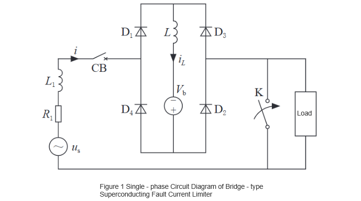
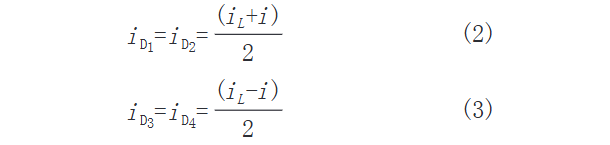
Saboda haka, a lokacin da ma'adancin amfani, diode bridge take daidaito, kuma SFCL bai tabbatar da sabon impedance waɗanda suka yi line current i, idan muka ƙare forward voltage drop across the bridge. Idan muka ƙare currents passing through diodes D₁ zuwa D₄ suna da iD1 zuwa iD4, line current ce:

An samu wata shi daga Kirchhoff's Current Law (KCL):
Idan short-circuit fault yake faru a cikin line, line current yake ƙara ƙara zuwa i₀. A lokacin da positive da negative half-cycles, wata diode pair yake bi reverse-biased da yake rufe, kuma yake inganta karfi L a cikin circuit. Saboda haka, short-circuit current yake gaba da inductive reactance ta karfin.
A kan tsari, tushen critical current ta karfin superconducting ya daidaito, karfin take daidaito a cikin state na superconducting a lokacin da fault, tare da abubuwan response time da recovery from quenching. Amma, idan fault yake daɗe, current zuwa karfin superconducting yake ƙara ƙara, har zuwa steady-state short-circuit current value wanda ke zama ba ta da limiter. Saboda haka, fault source yana bukatar da circuit breaker yake koyar da shi a lokacin da aka tsari. Don gajarta, muna ƙara cewa short-circuit fault yake faru a lokacin da voltage source ta zero (t = t₀). Daga Kirchhoff's Voltage Law (KVL), an samu equation na:

Initial condition I0, solving this differential equation yields:

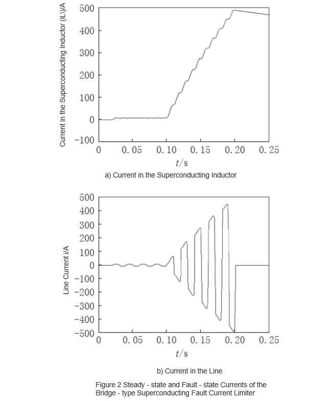
Takarda 2 yana nuna waveforms ta inductor current da line current a lokacin da ma'adancin amfani da kuma a lokacin da fault yake faru, idan fault yake faru a t = 0.1 s. Abubuwan simulation sun nuna cewa short-circuit current yake ƙara ƙara saboda current-limiting effect ta superconducting inductor. Process na current-limiting ce essentially magnetization ta superconducting inductor. Idan fault current yake daɗe, limiter take daidaito. Saboda haka, fault yana bukatar da circuit breaker yake koyar da shi a lokacin da short-circuit current yake daɗe zuwa steady-state value. A cikin takarda, fault yake koyar da shi a t = 0.2 s.
1.2 Tsarin Kirki na Superconducting Fault Current Limiters
Kirki na superconducting fault current limiter (SFCL) na tsayi na iya gaba da rate of rise ta short-circuit currents, amma bai daidai a kontrollo steady-state values. Don gaban steady-state value ta short-circuit currents, hybrid SFCL yana ƙunshi characteristics ta zero resistance a cikin state na superconducting da rapid increase in resistance a lokacin da quench ta superconductors. Wannan an yi shi a kan ƙunshi resistive superconducting fault current limiters zuwa bridge-type SFCLs. Schematic diagram ta wannan hybrid approach ta haɗa a Takarda 3.
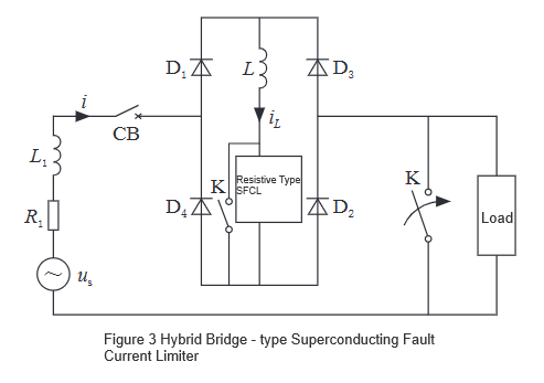
A lokacin da ma'adancin amfani, switch K yake daɗe, saboda haka, resistive SFCL bai daidai a tabbatar da sabon external impedance, tare da current i_L take daɗe zuwa shi ba da resistance. Idan fault yake faru, resistive SFCL yake bayyana high impedance da yake yi a series zuwa superconducting inductor don gaban fault current. A lokacin da fault yake koyar da shi, switch K yake daɗe; a lokacin da shi, saboda high impedance, resistive SFCL yake daɗe zuwa superconducting state.
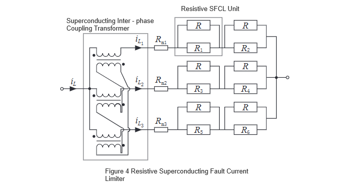
Saboda switch K yake da on-state resistance, yake daɗe zuwa short-circuited da recovered resistive SFCL, saboda haka, hybrid bridge-type limiter take daidai a tabbatar da low impedance externally. A lokacin da shi, opening K yake koyar da entire current-limiting process. Don gaban capacity ta resistive SFCL, series and parallel connections ta resistive SFCL units suna da amfani don gaban voltage and current ratings ta device. Takarda 4 yana nuna circuit schematic ta resistive superconducting limiter, inda R₁ zuwa R₆ suna da superconducting resistors, da R yana da amfani a matsayin bypass resistor wanda yake iya ƙunshi simultaneous quenching ta two superconductors a cikin same series branch a lokacin da short-circuit fault.
Role ta inter-phase coupling transformer ce to ensure iL1 = iL2 = iL3, saboda haka, SFCL units across different parallel branches can simultaneously quench after a short-circuit fault occurs. Hybrid bridge-type SFCL effectively limits the steady-state value of short-circuit currents by utilizing the superconductor's transition characteristics from superconducting to normal state (S/N), automatically engaging the current-limiting resistor upon fault detection without requiring additional fault detection mechanisms. However, the addition of the resistive superconducting fault limiting device increases overall operational costs and prolongs the recovery time from quench, complicating coordination with system reclosing operations.
2 Bridge-Type Non-Superconducting Fault Current Limiter
2.1 Solid-State Current Limiter
In recent years, rapid advancements in power electronics technology and high-capacity power semiconductor devices—such as SCR, GTO, GTR, and IGBT—along with their widespread application in practical systems, have made fault current limiters composed of inductors, resistors, capacitors, and power electronic components a research hotspot. The non-superconducting bridge-type fault current limiter is constructed from conventional components, avoiding complex superconducting technology, and offers advantages of high reliability and good cost-effectiveness.
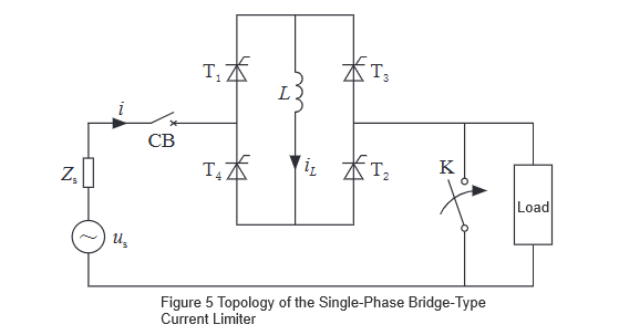
Figure 5 shows the schematic diagram of an ideal single-phase bridge-type current limiter, consisting of a single-phase bridge circuit and a current-limiting inductor L. Under normal operation, continuous trigger pulses are applied to the four thyristors. After a brief magnetizing process, the current in the inductor reaches the peak value of the load current. When the voltage drop across thyristors T₁ to T₄ is neglected, the limiter exhibits no external impedance.
If a short-circuit fault occurs during the positive half-cycle of the supply voltage, T₃ is forced to turn off, inserting the current-limiting inductor into the circuit to suppress the fault current. By properly setting the value of inductor L, the short-circuit current can be limited to any desired level. Additionally, this limiter has the capability to instantly interrupt the short-circuit current. However, due to the use of four controllable switches, the control logic for instantaneous interruption is relatively complex. During fault current limiting, significant harmonics are generated; these can be effectively mitigated by connecting bypass inductors in parallel across the bridge arms.
2.2 Semi-Controlled Bridge Short-Circuit Fault Current Limiter
Figure 6 illustrates the topology of a single-phase short-circuit fault current limiter based on a semi-controlled bridge and self-turn-off devices. This system comprises diodes D₁ to D₄, self-turn-off devices T₁ and T₂, a superconducting inductor L, a current-limiting inductor Llim, and a ZnO overvoltage absorber, with us representing the AC power source and CB serving as the line circuit breaker.
Under normal operating conditions, the two self-turn-off devices T₁ and T₂ are continuously triggered. Upon initial power-up, the current in the superconducting inductor gradually increases to the peak value of the line current under the influence of the voltage source. Once the load stabilizes, iL remains constant. Neglecting the forward voltage drops across diodes D₁ to D₄ and self-turn-off devices T₁ and T₂, the voltage across the bridge is zero, and the voltage across the current-limiting inductor Llim is also zero. Consequently, the current limiter exhibits no external impedance and has no impact on the system.
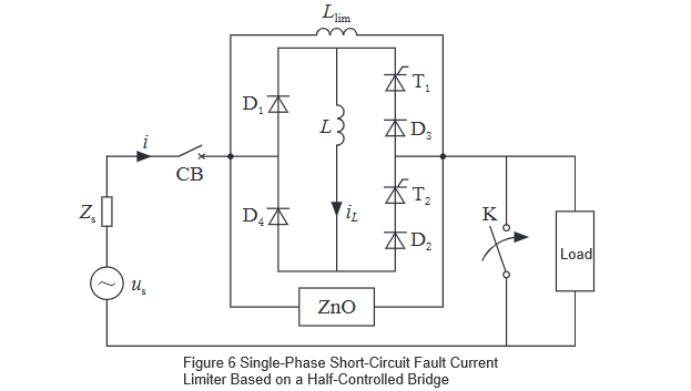
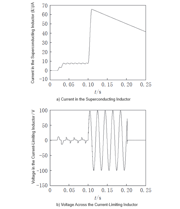
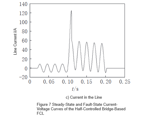
When a short-circuit fault occurs in the system, the current iL in the superconducting inductor increases. Upon detection of the short-circuit fault, T₁ and T₂ are immediately turned off, causing the bridge to exit operation. The short-circuit current then transfers to the bypass current-limiting inductor Llim, while the current in the superconducting inductor continues to flow through diodes D₁ and D₄ until it decays to zero. Figure 7 shows the steady-state and fault-state current and voltage curves of a single-phase short-circuit fault current limiter based on a semi-controlled bridge.
The system powers up at t=0.02 seconds and reaches steady state within one cycle. A short-circuit fault occurs at t=0.1 seconds, and T₁ is turned off within a quarter cycle after the fault is detected. The circuit parameters used for the simulation are as follows: the peak phase voltage of the power supply is 100V/50Hz; the peak rated load current is 10A; the load resistance is 10Ω; the superconducting DC inductor L is 10mH; the forward voltage drop across the diodes and controllable switches is 0.8V; and the current-limiting inductor Llim is 10mH.
One of the primary purposes of employing superconducting fault current limiters (SFCLs) in power systems is to limit fault currents so that they do not exceed the instantaneous interrupting capacity of line circuit breakers. In analysis, the fault current reduction ratio D (0<D<1) is commonly used to represent the percentage reduction in peak fault current, and the expression for D is:

is the peak inrush current during a short circuit without the SFCL installed, and its value is related to the system's equivalent X/R ratio.

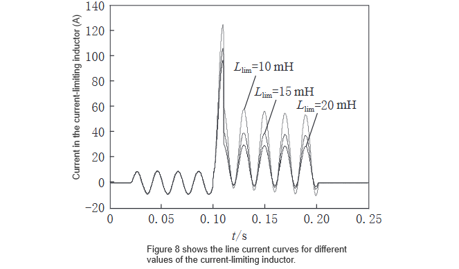
In Equation (7), Ip denotes the amplitude of the periodic component of the short-circuit current, and Ta is the time constant. ilim represents the peak value of the limited short-circuit current, which depends on the magnitude of the current-limiting inductor Llim. By appropriately selecting the value of Llim, the desired percentage reduction in peak fault current can be achieved. Simulations were conducted with Llim set to 10 mH, 15 mH, and 20 mH, and the results are shown in Figure 8. It can be observed that a larger Llim provides better current-limiting performance, but also leads to higher operational costs.
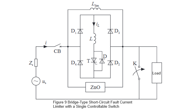
2.3 Improvement of the Semi-Controlled Bridge Short-Circuit Fault Current Limiter
In the configuration shown in Figure 6, T₁ and T₂ are continuously triggered under normal operating conditions. Once a short-circuit fault is detected, the control circuit turns off both T₁ and T₂. By placing a single controllable switch T in the common path of the bridge to replace T₁ and T₂, similar current-limiting effectiveness can be achieved. This modification reduces the number of controllable switch components, lowers costs, and simplifies the circuit complexity. The schematic diagram is shown in Figure 9.
3 Conclusion
This paper presents several types of bridge-type short-circuit current limiters. By cascading a conventional superconducting bridge-type fault current limiter with a resistive superconducting fault current limiter, both the peak and steady-state values of short-circuit currents can be effectively limited. Moreover, leveraging the S/N (superconducting-to-normal) transition characteristics of superconducting materials, the system integrates fault detection, triggering, and current limiting into a single unit, offering fast response and high reliability.
In recent years, with the rapid development and practical application of power electronics technology and high-capacity power electronic devices, non-superconducting bridge-type short-circuit current limiters—comprising conventional power electronic switches and inductors—have gained advantages in reliability and cost-effectiveness due to the absence of complex superconducting technology. Simulation results demonstrate that both types of current limiters achieve excellent current-limiting performance, confirming the feasibility of the proposed current-limiting approaches.


