
1. Karamin Da System Ta A Cikin Da Ba A Cikin CLiP (Current-Limiting Device)
A kananan yadda da aka yi aiki, switchboard ya yi aiki haka:
A cikin wannan gyaran, da ba a iya da shi fault current ta switchboard ita ce mafi tsawo 50kA. Saboda haka, current-limiting device (CLiP) ba a ji a cikin circuit ba.
A lokacin da ake yi aiki mai gaba-gaban da ke sauya wata generator (wanda ake karfin ta), kuma ake magana da wata (wanda ake synchronize da kuma ake magana ta), system ya yi aiki haka:
A cikin wannan alamun, short-circuit capacity ta system ya zama mafi, kuma da ba a iya da shi fault current ya yi fadada 50kA. Saboda short-circuit withstand rating ta switchboard ita ce 50kA, current-limiting device ya kamata a ji a cikin circuit don tabbatar da dalilin aiki.
CLiP ya yi nuna rate da current ya ƙarewa a lokacin. Idan current ya yi fadada ma'ana an bayar, device ya faru kuma ya koye bus connection ta hanyar melten internal fuse element. Wannan ya ƙarewa actual fault current a kan mafi tsawo 50kA, wanda ya bincike a cikin safe design limits ta switchboard.
Wannan prosesin ya ba da abin da take isole fault without causing a blackout of the entire eHouse power distribution system.
Marya:
2. Operation and Maintenance Requirements
Owner ta facility ya kamata ake amfani da proposed alternative operating arrangements. Farkon da za su iya haɗa suna da data masu inganci game da current-limiting fuse, including maintenance requirements, estimated service life, and the capability of personnel performing equipment maintenance. Duk waɗannan ayyukan za su buɗe a cikin operation and maintenance manual.
3. Design and Testing of the Current-Limiting Fuse
Current-limiting fuse ya kamata a yi aiki da testing according to recognized standards such as IEC 60282-1:2009/2014 and IEEE C37.41 series, and shall be suitable for the intended application and environmental/operational conditions. Only a single current-limiting fuse shall be used; any combination of current-limiting devices requires special consideration and evaluation.
CLiP has obtained KEMA type test reports covering breaking capacity, temperature rise, and insulation tests, along with calibration records for measuring equipment. Testing has been performed in compliance with IEC 60282 and ANSI/IEEE C37.40 series standards.
4. Insulation Level of the Fuse Holder
5. Verification of Fuse Suitability for Operating Temperature
The current-limiting fuse has been manufactured and tested in accordance with IEC 60282-1 or IEEE C37.41 series standards.
IEC 60282-1 specifies a maximum ambient temperature of 40°C, while the classification society standard SVR 4-1-1, Table 8, requires 45°C. Evidence compliant with Appendix E of IEC 60282-1 (or equivalent standards) must be provided to demonstrate that the fuse is suitable for the maximum expected ambient temperature of 45°C.
Testing covers the requirements of IEC 60282-1 and ANSI/IEEE C37.41. The Series II interruption test is more stringent than IEC requirements, as it demands 100% test voltage (IEC allows 87%). G&W tests Series I duties at 100% voltage and 100% current—exceeding all standard requirements. The actual project uses a 4000A rated device.
For a 5000A switchgear without forced cooling, the temperature rise margin is 5K at 40°C ambient, enabling it to carry 5000A at 40°C and 4000A at 50°C ambient.
6. Time-Current Characteristics and Current-Limiting Performance
This type of device does not have a conventional time-current curve (TCC). Its operation is completed within 0.01 seconds—well before the starting point of typical TCC curves—effectively making it an instantaneous device.
In practice, each application is evaluated on a case-by-case basis, using worst-case scenarios (fully asymmetrical faults). System currents are plotted with appropriate time resolution to clearly illustrate all interactions. This approach is superior to the potentially misleading use of peak let-through current curves.
7. Peak Overvoltage and Power Dissipation During High Fault Current Operation
According to IEC and ANSI/IEEE requirements for 15.5kV-rated equipment, the peak voltage during operation (maximum measured 47.1kV) remains within the 49kV range, and does not involve the release of large amounts of heat or steam associated with expulsion-type interruption.
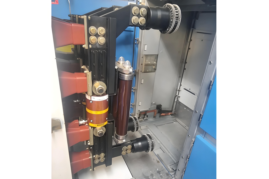
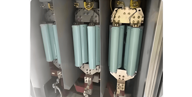
The CLiP's heat dissipation structure is essentially a busbar with machined current-limiting sections.
The total heat dissipation of a three-phase CLiP system at 4000A is approximately 500W.
8. Short-Circuit Study and Validation of Cascading Protection
The short-circuit study shall demonstrate the function of the current-limiting device and how it reduces the symmetrical fault current below the switchboard’s rated withstand level. If the proposed arrangement is intended to operate as "cascaded protection," compliance with the conditions specified in classification society standard SVR 4-8-2 / 9.3.6 must be verified. The selection of the triggering point and determination of let-through current in each direction shall be clearly defined.
9. Calculation of Busbar Withstand Capability for Maximum Short-Circuit Current
Calculations shall be performed in accordance with IEC standards to verify the busbar’s ability to withstand the mechanical and thermal effects caused by the maximum prospective short-circuit current.


