Introduzzjoni
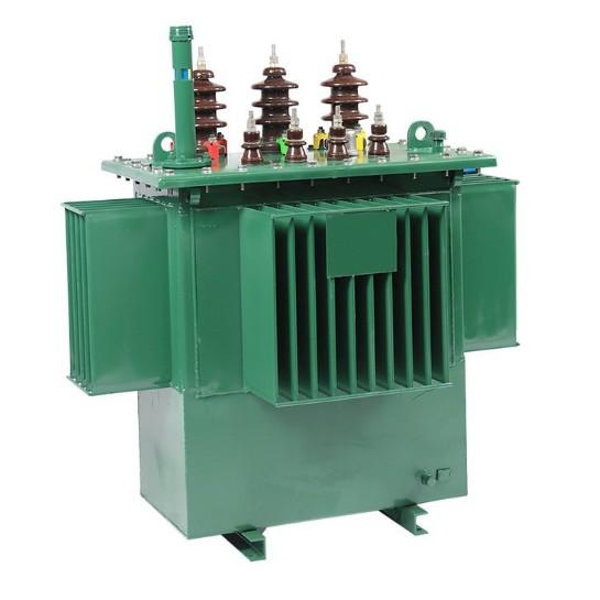
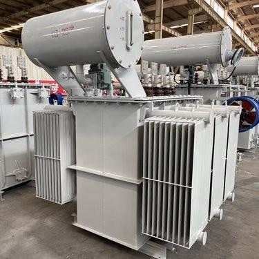
Fl-landskap komplikat tal-distribuzzjoni tal-kurrent, il-trasformaturi ta’ distribuzzjoni għandhom ruħa moxxena. Il-trasformaturi hawn hemm l-obbligazzjoni ta’ tneħħija tal-volttagġ mid-livelli primarji tad-distribuzzjoni għal livelli ta’ utilizzazzjoni adattati għall-utenti finali. L-funzionament tagħhom propju huwa essenzjali biex jinsab stabilità u effiċjenza fil-grażz ta’ kurrent. Din l-artiklu tindakka f’due aspetti essenzjali tas-silġ tal-trasformaturi ta’ distribuzzjoni: it-test ta’ prestazzjoni termika u it-test ta’ prestazzjoni mekanika, waqt li tistqarr ukoll kif jistgħu jiġu prevenuti l-interruzzjonijiet tas-servizz u kif jistgħu jiġu gestiti l-varjazzjonijiet tal-volttagġ.
It-Test ta’ Prestazzjoni Termika tal-Trasformaturi ta’ Distribuzzjoni
L-Importanza tal-Ispezzjoni Termika
Il-trasformaturi ta’ distribuzzjoni jġeneraw ħalib fl-operazzjoni. Il-ħalib huwa prodott b’mod preponderanti minn perditi tal-windings u histereżis tal-nukelu fil-trasformaturi. L-akkumulazzjoni mhux kontrollata tal-ħalib fit-trasformaturi tista’ tiddegradaxxi l-izolazzjoni, taccelera l-proċess ta’ invecchi jew tpoġġi r-riskju sovrastant ta’ falliment katastrofiċi. Ispezzjonijiet termiki regolari fit-trasformaturi huma allura ta’ importanza estrema. Dawn is-ispezzjonijiet, li jinkludu monitoraġġ tal-temperatur u dettazzjoni ta’ posti ħalba fit-trasformaturi, jagħmlu funzjoni ta’ sistemi ta’ avvertiment prekku. Bil-identifikazzjoni tempestiva ta’ anomali termiki fit-trasformaturi, i-teknici jistgħu jprevedixxu l-kollaps u jagħtux assiġurazzjoni tas-servizz kontinwu permezz tad-distribuzzjoni.
Komponenti Eseguttivi ta’ Test Termiku għat-Trasformaturi
Diversi tests jagħmlu l-bażi għal ispezzjonijiet tal-prestazzjoni termika għat-trasformaturi ta’ distribuzzjoni:
Test tal-Aument tal-Temperatura: Ispezzjoni fundamentali għat-trasformaturi, dan it-test imqaddem il-misurazzjoni tal-aument tal-temperatura fil-windings u l-oli tal-trasformaturi taħt il-kariga ratificata. Divergenzi mill-standardi stabiliti fil-trasformaturi jissemaljaw problemi potenzjalji bħal raffreddament ineffiċjenti jew problemi ta’ reżistanza interna. Dan jagħmel inspezzjoni magħrufa tal-komponenti bħal ventilaturi, fini, jew livelli ta’ raffreddant fil-trasformaturi.
Ispezzjoni tal-Immaġini Termike: Kammeri infrarossi huma impiegati fi dani metodu ta’ ispezzjoni non-invasiva għat-trasformaturi. Huma jmapjaw it-temperatur tas-superficji tal-trasformaturi, jispotlightaw l-posti ħalba nascosti, li jistgħu inkunu xejrin minn konnessjonijiet miftuħa jew duttat blokkati fil-trasformaturi. Dan jaqra lil riparazzjonijiet mirati fil-trasformaturi qabel li sseħħ id-danni tal-izolazzjoni.
Analisi tal-Temperatura tal-Oli: Tampun tal-oli tal-trasformaturi u l-test tal-viskożità u l-kontenut ta’ aċidu jagħmlu kunċett dwar l-livelli ta’ stress termiku esperjenza mill-trasformaturi. Livell elevat ta’ aċidita’ fis-silġ tal-oli tal-trasformaturi jindika skondi eccessivi, li jistimina l-ispezzjoni tal-sors ta’ ħalib u mekanismi ta’ raffreddament fil-trasformaturi.
Protokolli u Standardi għat-Ispezzjonijiet tal-Trasformaturi
Standardi bħal IEEE C57.12.90 u IEC 60076 jordna ispezzjonijiet termiki sistematiċi għat-trasformaturi. Fiż-żmien tat-test, it-teknici jsimulaw kondizzjonijiet ta’ kariga fulla fil-trasformaturi waqt li jmonitorjaw daqs gradjenti ta’ temperatur. Pereżempju, ispezzjoni tal-aument tal-temperatur fil-trasformaturi treġeb stabilizzazzjoni tal-trasformaturi għal ftit ore qabel l-irreġistrazzjoni tal-readings. Id-dokumentazzjoni dettaljata ta’ kull ispezzjoni tal-trasformaturi, inklużi l-kondizzjonijiet ambientali, id-durazzjoni tal-tests, u l-profili termiki, ifassilja l-analisi tal-trendi tal-trasformaturi fil-ħin.
Freqwenza u Strategiji Adattivi għat-Ispezzjonijiet tal-Trasformaturi
Il-freqwenza tal-ispezzjonijiet termiki għat-trasformaturi tdependi minn diversi fatturi bħal varjabbiltà tal-kariga u kondizzjonijiet ambientali. Il-trasformaturi ta’ distribuzzjoni f’dawk areas urbanijiet bil-karigi fluttwanti jistgħu jirequirenu ispezzjonijiet mensili, waqt li dawk f’dawk areas rurali jistgħu jkunu suffiċjenti ma’ verifiki trijali. Fl-klimgi ħalba, il-periodi bejn ispezzjonijiet termiki għat-trasformaturi jkunu qasri biex jkontrabbilancjaw l-effetti tal-stress termiku. Sistemi avvanzati ta’ monitoraġġ issa jippermettu ispezzjonijiet termiki kontinwi għat-trasformaturi permezz sensuri embeddi, li jtrasmettu data real-time mill-trasformaturi għal centers ta’ kontrol.
Ttajbat tal-Sfidi f’t-Ispezzjonijiet tal-Trasformaturi
Ispezzjonijiet termiki għat-trasformaturi jiffaċċjaw sfidi żgħar. Notabilment, possibli jkunu falsi pozitivi minħabba spajki transjentijiet ta’ kariga fil-trasformaturi. Biex jintieħdu dawn, it-teknici jkorellagħaw id-data termika mal-parametri elektriki, bħal kurrenti ta’ kariga fil-trasformaturi. F’dan il-mod, l-aċċess għal komponenti diffiċli l-għadha, bħal windings interni fil-trasformaturi, jirequire espertizza specializzata. Dawn is-spezzjonijiet tal-trasformaturi jistgħu jirequirenu tħassir tal-oli, li jistimina l-aderenza strikta għal protokolli ta’ sigurtà metiku. Il-kalibratura regolari tas-sensuri termiki fil-trasformaturi tagħti r-garanzija ta’ riżultati ta’ ispezzjoni akkurati.
Integrazzjoni tal-Ispezzjoni Termika mal-Manutenzjoni tal-Trasformaturi
Ispezzjonijiet termiki għat-trasformaturi jagħmlu funzjoni ta’ pont għal t-talbien ta’ data u azjonijiet ta’ manutenzjoni. R-rapport ta’ ispezzjoni komplet tal-trasformaturi, li jflagga posti ħalba, ineffiċjienza ta’ raffreddament, jew degradazzjoni tal-oli, jagħti direzzjonijiet għal interventi immediati. Pereżempju, jekk ispezzjoni ta’ immaġini termike t揭示了变压器冷却翅片堵塞的情况,清洁或更换就成为优先事项。通过将热检测纳入变压器的预防性维护计划中,操作人员可以延长变压器的使用寿命并减少电网的脆弱性。
Distribution Transformers Mechanical Performance Testing
The Indispensability of Mechanical Inspection for Transformers
Throughout their lifecycle, distribution transformers are subjected to mechanical stresses. Electrical faults can generate intense electromagnetic forces that may distort the windings of the transformers. Additionally, seismic activity or rough handling during transportation can damage internal components of the transformers. Regular mechanical inspections, ranging from visual checks to dynamic testing of the transformers, are essential for detecting hidden flaws. By identifying mechanical weaknesses early in the transformers, operators can safeguard against sudden breakdowns that could disrupt power supply and endanger the overall infrastructure reliant on these transformers.
Core Mechanical Testing Components for Transformers
Several tests are integral to mechanical performance inspections of distribution transformers:
Short-Circuit Impulse Test: This inspection simulates fault conditions to assess the ability of the transformers to withstand electromagnetic forces. Deviations in impedance or winding displacement in the transformers signal mechanical stress, prompting an inspection of clamping structures and support frames within the transformers.
Vibration Analysis Inspection: Sensors are used to monitor vibrations during the operation of the transformers. Abnormal frequencies detected in the transformers indicate issues such as loose parts, misaligned cores, or damaged cooling fans. This non-invasive inspection method helps technicians pinpoint and rectify mechanical issues in the transformers before they escalate.
Mechanical Impact Test: Applied during the manufacturing process or after the transportation of the transformers, this test evaluates the resilience of the transformers to shocks. Drop tests or seismic simulations reveal vulnerabilities in components like the tank, bushings, or terminal connections of the transformers, triggering inspections of critical joints.
Inspection Protocols and Standards for Transformers
Standards like IEEE C57.12.90 and IEC 61378 mandate rigorous mechanical inspections of transformers. During testing, technicians follow precise procedures. For example, short-circuit tests in transformers require controlled current injections while closely monitoring the mechanical responses of the transformers. Detailed documentation of each inspection of the transformers, including test parameters, observed deformations, and repair recommendations, builds a historical record for future analysis of the transformers.
Frequency and Contextual Adaptation for Transformer Inspections
The frequency of mechanical inspections for transformers varies based on usage scenarios. Distribution transformers in earthquake-prone regions may undergo quarterly vibration inspections, while those in stable environments could suffice with annual checks. Newly installed transformers often receive immediate post-transport inspections to verify their integrity. Advanced monitoring systems now enable continuous mechanical inspections of transformers via embedded strain gauges and accelerometers.
Overcoming Inspection Challenges in Transformers
Mechanical inspections of transformers come with their own complexities. Detecting internal damage without disassembling the transformers is a significant hurdle. Some inspections, such as ultrasonic testing for hidden cracks in the transformers, require specialized expertise. Additionally, differentiating normal wear from abnormal degradation in the transformers demands experience. To address these challenges, technicians combine multiple inspection methods, such as vibration analysis with visual inspections, and leverage historical data for comparative assessments of the transformers.
Integrating Mechanical Inspection with Transformer Maintenance
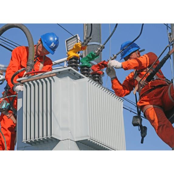
Mechanical inspections of transformers serve as a crucial link between diagnosis and action. A comprehensive inspection report of the transformers, which flags issues like loose bolts, deformed windings, or compromised supports, dictates urgent repairs or component replacements. For example, if a vibration inspection reveals a misaligned core in a transformer, realignment and retightening become top priorities. By embedding mechanical inspections into the preventive maintenance schedules of the transformers, operators can extend the lifespans of the transformers and fortify grid resilience.
Preventing an Interruption of Service in Distribution Transformers
How Transformers, Secondaries, and Fuses Operate
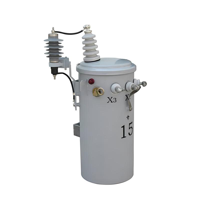
Distribution transformers step down voltage from the distribution or primary feeder voltage to the utilization voltage. They are connected to the primary feeder, sub-feeders, and laterals through primary fuses or fused cutouts. The primary fuse disconnects its associated distribution transformer from the primary feeder when a transformer fault or low-impedance secondary-circuit fault occurs. Fused cutouts, which are normally closed, provide a convenient means for disconnecting small distribution transformers for inspection and maintenance.
Satisfactory overload protection of a distribution transformer cannot be achieved with a primary fuse alone. This is due to the difference in the shape of its current-time curve and the safe current-time curve of a distribution transformer. If a small enough fuse is used to offer complete overload protection for the transformer, much of the valuable transformer overload capacity is lost as the fuse blows prematurely. Such a small fuse also frequently blows unnecessarily on surge currents. Therefore, a primary fuse should be selected based on providing short-circuit protection only, with its minimum blowing current usually exceeding 200% of the full load current of its associated transformer.
Distribution transformers connected to overhead open-wire feeders are often subjected to severe lightning disturbances. To minimize insulation breakdown and transformer failures from lightning, lightning arresters are commonly used with these transformers.
The secondary leads of a distribution transformer are typically solidly connected to radial secondary circuits, from which consumer services are tapped. This means that the transformer lacks protection against overloads and high-impedance faults on its secondary circuits. Relatively few distribution transformers are burned out by overloads, mainly because they are often not fully utilized to their overload capacity. Another factor contributing to the low number of overload-related failures is the frequent load checks and corrective measures taken before dangerous overloads occur. However, high impedance faults on their secondary circuits likely cause more distribution transformer failures than overloads, especially in areas with poor tree conditions.
Fuses in the secondary leads of distribution transformers are little more effective in preventing transformer burnouts than primary fuses, for similar reasons. The proper way to obtain satisfactory protection for a distribution transformer against overloads and high-impedance faults is by installing a circuit breaker in the secondary leads of the transformer. The tripping curve of this circuit breaker must be properly coordinated with the safe current-time curve of the transformer. The primary fuse must also be coordinated with the secondary breaker so that the breaker trips on any current that can pass through it before the fuse is damaged.
Faults on a consumer’s service connection from the secondary circuit to the service switch are extremely rare. Thus, the use of a secondary fuse at the point where the service connection taps onto the secondary circuit is not economically justifiable, except in unusual cases such as large services from underground secondaries.
Voltage Variation Considerations
Assuming a maximum voltage variation of about 10% at any consumer’s service switch, the division of this drop among the various parts of the system, at full load, may be approximately as follows:
2% voltage variation in the primary feeder between the first and last transformers
2.5% voltage variation in the distribution transformer
3% voltage variation in the secondary circuit
0.5% voltage variation in the consumer’s service connection
The fact that the voltage at the primary of the first distribution transformer cannot ordinarily be maintained exactly accounts for the other 2%.
These figures are typical for overhead systems supplying residential loads. However, they can be expected to differ significantly in underground systems where cable circuits and large distribution transformers are used, or when supplying industrial and commercial loads.
The economic size of the distribution transformer and secondary-circuit combination for any uniform load density and type of construction, at specific market prices, can be readily determined once the total allowable voltage drop in these two parts of the system is established. If the transformer is too large, the secondary circuit cost and total cost will be excessive. Conversely, if the transformer is too small, the transformer cost and total cost will be too high.
Handling Load Changes in Transformers
As in any other part of the distribution system, load change or load growth must be considered and planned for in distribution transformers and secondary circuits. Distribution transformers and secondary circuits are not installed merely to serve the loads existing at the time of installation but also to accommodate some future loads. However, it is not economical to make excessive allowance for growth.
When a distribution transformer becomes dangerously overloaded, it can be replaced by one of the next larger size if the current-carrying capacity of the secondary circuit and the overall voltage regulation permit. If not, another transformer of about the same size can be installed between the overloaded transformer and the adjacent one. This involves removing load from the overloaded transformer by connecting part of its secondary circuit and associated load to the new transformer. This also reduces the load on the secondary circuit of the overloaded transformer and improves the overall voltage regulation. In areas with reasonably uniform load, transformers may need to be installed on both sides of the overloaded transformer relatively quickly to maintain satisfactory voltage conditions and prevent overloading parts of the secondary circuit. The same result can also be achieved by installing one new transformer and relocating the overloaded transformer so that it feeds into the center of its shortened secondary circuit.
Transformer Banking for Service Improvement
With distribution transformers and secondary circuits arranged as in the typical radial configuration, any one load is supplied through only one transformer and in only one direction over the secondary circuit. Because of this, a suddenly applied load, such as when starting a motor, on a consumer’s service can cause objectionable light flicker on other consumers’ services fed from the same transformer. The increasing use of motor-driven appliances in residential areas is resulting in a significant number of light-flicker complaints. In some areas, light flicker, rather than voltage regulation, may be the determining factor in the size and arrangement of transformers and secondary circuits.
The banking of distribution transformers is usually the best and most economical means of improving or eliminating light flicker. Banking transformers means paralleling on the secondary side a number of transformers all connected to the same primary circuit. The secondary circuit arrangement in a banked transformer layout can take various forms, such as loops or grids similar to those used in a secondary network system. However, banked transformers, being connected to and supplied over a single radial-primary feeder, are a form of radial distribution system, unlike a secondary network loop or grid which is supplied over two or more primary feeders and offers much greater service reliability.
The conversion from the usual radial secondary circuit arrangement to the banked-transformer arrangement can usually be done simply and cheaply by closing the gaps between the radial secondaries of a number of transformers associated with the same primary feeder and installing the proper primary and secondary fuses.
Protection in Transformer Banking
Two major forms of protection have been used when banking distribution transformers. The first arrangement, which is probably the oldest and most common, involves connecting the distribution transformers to the primary feeder through primary fuses or fused cutouts. These fuses should blow only on a fault in their associated transformer. All transformers are connected to the common secondary circuit through secondary fuses, whose purpose is to disconnect a faulty transformer from the secondary circuit. The size of the secondary fuse must be such that it will blow on a primary fault between its transformer and the associated primary fuse. Faults on the secondary circuit are normally expected to burn themselves clear. To prevent frequent blowing of secondary fuses on secondary-circuit faults, these fuses should have relatively long blowing times on all fault currents, but not so long as to fail to provide some protection to the transformers against secondary faults that do not clear quickly.
Using a secondary breaker with proper current-time characteristics is preferable to secondary fuses when banking transformers as it offers greater protection to the transformer against overloads and high-impedance faults. The secondary fuses or breakers should open in less time than the primary fuses on any possible current to prevent the blowing of primary fuses on a secondary fault.
A transformer fault is cleared by the transformer’s primary and secondary fuses without interrupting service. Most secondary faults clear quickly, but when a secondary fault persists, several or all of the secondary fuses may blow and some transformers may be burned out. Experience shows that with careful study of expected fault currents and proper selection of primary and secondary fuses, this method of banking operates with minimal issues. However, occasionally a secondary-circuit fault causes multiple secondary fuses to blow and some transformers to burn out, resulting in a greater service interruption than with radial secondary circuits.
The second transformer banking arrangement is preferable as there is no danger of a complete service interruption to the banked area due to a secondary fault. In this arrangement, distribution transformers are connected to the primary feeder through primary fuses for the same reasons as in the first arrangement. The transformers are solidly connected to the secondary circuit, which is sectionalized between transformers by secondary fuses. These fuses are selected to blow quicker than any primary fuse for any secondary-circuit fault. When a transformer fails, it is removed from the system by its primary fuse and the adjacent secondary fuses on either side. Thus, a transformer fault results in a service interruption only for the consumers associated with the faulty transformer. A secondary-circuit fault usually burns clear, but if it persists, it is cleared by the secondary fuses next to the faulty section and the primary fuse of the associated transformer. The secondary fuses are typically selected to operate even on high-impedance faults, while the primary fuses are not, for the reasons discussed earlier regarding radial-secondary circuits. This ensures that even with a persistent high-impedance fault, the adjacent secondary fuses blow and prevent service interruption on the unaffected secondary sections, although the associated transformer may be burned out. To prevent this, a secondary breaker with a current-time curve coordinated with the safe current-time curve of the transformer can be used in the secondary leads of the transformer. When such a breaker is used, the secondary fuses must be selected so that their blowing times for all fault currents are less than the tripping times of the breakers.
Normally, the two banking arrangements function similarly. They reduce or eliminate light flicker and improve voltage regulation or allow for a reduction in the amount of transformer capacity required compared to radial-secondary circuits. This improvement is due to tying several radial-secondary circuits together and taking advantage of the diversity among different consumer groups. A significant increase in the use of banked transformers can be expected in the future, as these advantages can often be achieved at no additional cost or with a saving compared to the usual radial secondary-circuit arrangement.
In conclusion, both thermal and mechanical performance testing of distribution transformers are crucial for maintaining the reliability and longevity of these essential components in the power distribution system. By understanding their operational characteristics, implementing proper inspection and protection measures, and addressing issues such as voltage variation and load growth, we can ensure a stable and efficient power supply for consumers.


