Sarrera
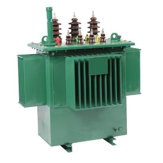
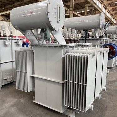
Indar banatzearen konplexu-egoeran, banatzaile transformatorrek erabateko rolak jolasten dute. Transformatore horiek zailtasun handiko arrakasta duten funtzioa duen arren, eguneroko lanak eta prozesuak askoz gehiago dituzte. Transformatore horiek zailtasun handiko arrakasta duten funtzioa duen arren, eguneroko lanak eta prozesuak askoz gehiago dituzte. Artikulu honek bi alde esentzialtan sakonduko da: transformadoreen errendamendu termikoaren eta mekanikoaren ebaluazioa, zerbitzu itxurak eta tentsio aldaketak nola saihesteko.
Banatzaile Transformadoreen Errendamendu Termikoaren Ebaluazioa
Termika Inspektibako Garrantzia
Banatzaile transformadoreek kalor sortzen dute lan egitean. Kalor hau gertatzen da transformadoreen biraka eta nukleoaren histeresisagatik. Kalor kontrolik gabeko bildumak transformadoreen isulagarrari eta enpresioari eragin dezake, transformadoreen zaharregara azeleratuz. Hori dela eta, transformadoreen inspektibako termikoak oso garrantzitsuak dira. Inspektibako horiek, transformadoreen tenperatura kudeaketa eta puntu gorriak detektatzeko, agindu lehengo sistema bat direla esan behar da. Transformadoreen termika anomaliak azkar identifikatuz, teknikariak ezin dute zaharregara eraman eta indar esteka jarraitua lortzeko laguntzen dute.
Transformadoreen Termika Ebaluazioen Oinarriko Testuak
Hainbat testu daude transformadoreen errendamendu termikoaren ebaluazioen oinarrian:
Tenperatura Handitzearen Testua: Testu fundamental horrek transformadoreen biraka eta oliaren tenperaturaren handitzea neurtzen du igoteko karga baten arabera. Desbideratzeak transformadoreen ohiko estandarrarekin, hondamendu orokorrak edo barruko erresistentziarako arazoak adieraz ditzake. Emaitza horrek transformadoreen osagai batzuei, hala nola, sasiketa erregeleki, finak edo likidoa, begirada gehigarria eskatzen dio.
Irudi Termikoaren Inspektibakoa: Infrarojo kameralari erabiliz, transformadoreen gaineko tenperaturak mapatzen ditu, puntu gorriak nabarmenduz, zuriuneen lotura askatuak edo kanal blokeatutako transformadoreen ondorioz. Horrek zuriuneen desgaste gabe egiten dute transformadoreen osagai batzuei zuzendu ahal izateko.
Oliaren Tenperaturaren Analisia: Transformadoreen oliaren bistilutasuna eta asidotasuna lagundu dute transformadoreen termika estresaren ulertzeko. Oliaren asidotasuna altua denean, transformadoreen barneko kalor handia adierazten du, transformadoreen barneko kalor iturriak eta sasiketa mekanismoak inspektatzea eskatzen du.
Transformadoreen Inspektibako Protokolak eta Estandarrak
IEEE C57.12.90 eta IEC 60076 estandarrak transformadoreen sistemakinspektibako termikoak eskatzen dituzte. Testuan, teknikariak simulatzen dute transformadoreen karga betearen egoera, tenperatura gradienteak zeharkatuz. Adibidez, tenperatura handitzearen inspektibakotan, transformadoreak ordu batzuetan stabilizatu behar dira datuak grabatzen hasi baino lehen. Inspektibako bakoitzaren dokumentazio zehatza, inguru egoera, testu iraupena eta termiko profila, transformadoreen tren analisia laguntzen du.
Transformadoreen Inspektibako Maiztasuna eta Estrategiak
Transformadoreen termika inspektibako maiztasuna kargaren aldaketaren eta inguru egoeraren arabera aldatzen da. Herriko transformadoreek kargaren aldaketak dituztenean, hilabetean inspektibakoak egin behar dira, baina herri txikiagoetan, lau hilabetean egin behar dira. Egoera hotan, inspektibako arteko tartea laburtu behar da kalor estresaren aurka. Oraindik, kontrol-zentroetara datuak transmititzen dituzten sensorrak transformadoreen barnean kokatuta daudela, inspektibako termikoak jarraitu egin daitezke.
Transformadoreen Inspektibako Arazoak
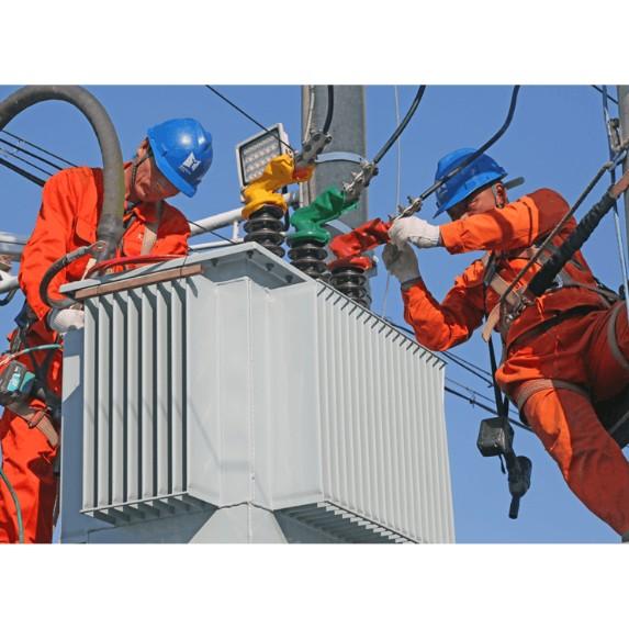
Transformadoreen termika inspektibakok arazo batzuk dituzte. Kasu baten, kargaren pikeak transformadoreen balio positibo faltsuak sortu ditzake. Arazo hori murrizteko, teknikariak termika datuak elektrikoki parametroak, hala nola, kargaren korrontea, elkartzen dituzte. Aldiz, erdi-barruko birakoen inspektibakoak, hainbat kasutan, oliak kendu beharrean, segurtasun protokolo zehatzak jarraitu behar dira. Termika sensorrak kalibratzea transformadoreen inspektibako emaitza zuzenen laguntzen du.
Inspektibako Termikoen Integratzea Transformadoreen Mantentzailearekin
Transformadoreen termika inspektibakok datu kolektibarekin eta mantentzaile ekintzarekin ponte bat dira. Inspektibako orokorra, transformadoreen puntu gorriak, sasiketa inefizientzia edo oliaren degradazioa adierazten du, ekintza zuzenak egiteko. Adibidez, baldin eta irudi termikoaren inspektibakok sasiketa fin blokeatua aurkitzen badu, garbitzea edo ordezpena prioritate bihurtzen da. Transformadoreen mantentzaile preventiboko planak integratuz, operariak transformadoreen bizitza luzatu eta sareko arrazoikotasuna murriztu ditzakete.
Banatzaile Transformadoreen Errendamendu Mekanikoaren Ebaluazioa
Transformadoreen Mekanika Inspektibakoaren Ezinbestekotasuna
Banatzaile transformadoreek mekanika presioei egongo dira haien bizitza osoan. Elektrikoki akatsak, transformadoreen birakoen deformazioak sor dezakete. Aldiz, seismologien aktibitatea edo transportazioan jaso zaitezkeen danborak, transformadoreen barruko osagaiak zauritu ditzakete. Mekanika inspektibakoak, ikusizko egokitzeko dinamikoki transformadoreen artean, espresioen aurkitzeko oso garrantzitsuak dira. Espresioen aurkitzeko aurretik, operariak ezin dute pertsona baten zerbitzuak eta sareko infraestruktura orokorra erraztu.
Mekanika Testuen Oinarriko Osagaiak Transformadoreentzat
Hainbat testu daude transformadoreen errendamendu mekanikoaren ebaluazioan:
Kontaktu Txikia Impulsuaren Testua: Testu horrek simula fault kondizioak, transformadoreen magnetiko-electrizko presioak suportatzeko gaitasuna ebaluatzen du. Transformadoreen impedimentuaren edo birakoen desplazamenduaren desbideratzeak, mekanika presioa adierazten du, transformadoreen klampatze estruktura eta sustapen markoak inspektatzea eskatzen du.
Zuhurren Analisiaren Inspektibakoa: Sensorrak erabiltzen dira transformadoreen lan egitean zuhurren monitorizatzeko. Zuhurren abnormala detektatzen denean, osagaien atzeratzea, nukleoaren desalineazioa edo sasiketa erregelekien zauritzea adierazten du. Horrela, teknikariak espresioen aurkitzeko eta zuzenduko dituzte transformadoreen barruko osagaiak.
Mekanika Arrakasta Testua: Testu horrek, transformadoreen fabrikazioan edo transportazioan, transformadoreen resistensia zauritzei ebaluatzen du. Testu horrek, transformadoreen tank, bushing edo terminal konektoreen debilgarritasuna aurkitzen du, transformadoreen osagai kritikoak inspektatzea eskatzen du.
Transformadoreen Inspektibako Protokolak eta Estandarrak
IEEE C57.12.90 eta IEC 61378 estandarrak transformadoreen sistemakinspektibako mekanikoak eskatzen dituzte. Testuan, teknikariak protokolo zehatzak jarraitzen dituzte. Adibidez, kontaktu txikia testuan, kontrolatuta, transformadoreen mekanika erantzunak zeharkatuz. Inspektibako bakoitzaren dokumentazio zehatza, testu parametroak, deformazioak eta konponketa proposamenak, transformadoreen historikoa analizatzeko laguntzen du.
Transformadoreen Inspektibako Maiztasuna eta Kontextualizazioa
Transformadoreen mekanika inspektibako maiztasuna erabilitako egoeren arabera aldatzen da. Seismologien probabilitate handiko eskualdeko transformadoreek, hilabetean zuhurren inspektibakoak egin behar dituzte, baina egoera estableskoetan, urtean egin behar dituzte. Instalatutako berriak, transportazioaren ostean, transformadoreen integritatea egiaztatzeko inspektibakoak egin behar dira. Oraindik, kontrol-zentroetara datuak transmititzen dituzten sensorrak transformadoreen barnean kokatuta daudela, inspektibako mekanikoak jarraitu egin daitezke.
Transformadoreen Inspektibako Arazoak
Transformadoreen mekanika inspektibakok arazo batzuk dituzte. Barruko zauritzeak, transformadoreen barnean, deskonposatuta, aurkitzea arazo handia da. Batzuei, ultrasonikotako testuak, transformadoreen barruko trinkak aurkitzeko, espertise espesiala beharrezkoa da. Aldiz, normala eta anormala desgastearen arteko bereizketa, transformadoreen artean, esperientzia beharrezkoa da. Arazo horiek konpontzeko, teknikariak hainbat inspektibako metodo elkartzeko, zuhurren analisiaren eta ikusizko inspektibakoaren artean, eta datu historikoen arabera, transformadoreen artean, konparazio egin ditzake.
Mekanika Inspektibakoaren Integratzea Transformadoreen Mantentzailearekin
Transformadoreen mekanika inspektibakok diagnostikoaren eta ekintzaren arteko ponte bat dira. Inspektibako orokorra, transformadoreen osagaien atzeratzea, birakoen deformazioa edo sustapen markoak, zuzeneko konponketa edo ordezpena eskatzen du. Adibidez, baldin eta zuhurren inspektibakok nukleoaren desalineazioa aurkitzen badu, alineazioa eta berriro apaintzea prioritate bihurtzen dira. Transformadoreen mantentzaile preventiboko planak integratuz, operariak transformadoreen bizitza luzatu eta sareko arrazoikotasuna fortifikatu ditzakete.
Zerbitzu Itxurak Saihesteko Banatzaile Transformadoreen Artean
Transformadoreak, Bigarrenak eta Fusetak Nola Lan Estuten
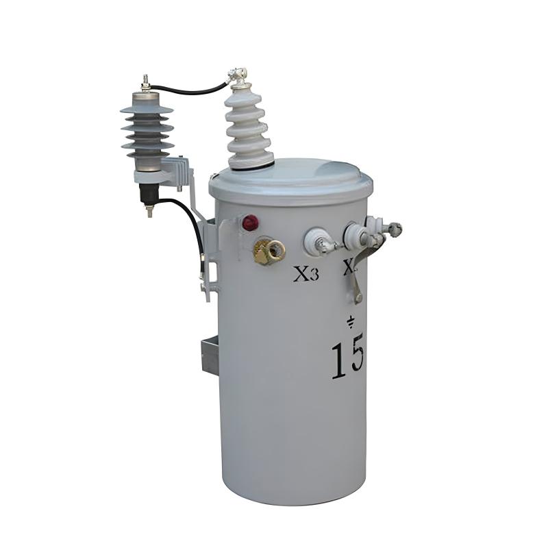
Banatzaile transformadoreek tensioa jaisten dute banatzailearen edo aurreko eramatearen tensiotik erabiltzailearentzako tensiora. Transformadore horiek aurreko eramateari, sub-eramateari eta lateralari lotuta daude aurreko fusen edo fuse cutout baten bidez. Aurreko fusek, transformadorearen edo bigarren-circuituaren fault bat gertatzen denean, bere transformadorea aurreko eramatearengatik kendu dute. Fuse cutout, normalean itxia, transformadore txikiak inspektatzeko eta mantentzeko modu bat ematen du.
Banatzaile transformadore baten overload protectiona, aurreko fuse bakarrekin, ez da lortu. Honek, bere corriente-tiempo kurba eta transformadorearen corriente-tiempo kurba arteko desberdintasuna delatzen du. Fuse txiki bat erabili bada, transformadorearen overload protection osoa emateko, transformadorearen balioa galduko da fuseak aurrealdian geratzeagatik. Horrela, aurreko fuse bat short-circuit protection soilik emateko hautatu behar da, bere minimum blowing current-ak, adina, 200% baino gehiago izan behar du bere transformadorearen full load current-aren gainean.
Banatzaile transformadoreek, aurreko eramatea open-wire eramatea badira, askotan thunderstormen eraginpean dauden. Thunderstormen eraginpean, transformadoreak insulation breakdown eta transformadoreen fail gertatzen dira. Lightning arresters erabili ohi dira transformadore horiekin.
Banatzaile transformadoreen bigarren leadsak, normalean, solidly connected radial secondary circuits, non consumer services eman dizkie. Honek, transformadoreak overloads eta high-impedance faults bigarren circuituan ez dute protection. Relatively few distribution transformers are burned out by overloads, mainly because they are often not fully utilized to their overload capacity. Another factor contributing to the low number of overload-related failures is the frequent load checks and corrective measures taken before dangerous overloads occur. However, high impedance faults on their secondary circuits likely cause more distribution transformer failures than overloads, especially in areas with poor tree conditions.
Fuses in the secondary leads of distribution transformers are little more effective in preventing transformer burnouts than primary fuses, for similar reasons. The proper way to obtain satisfactory protection for a distribution transformer against overloads and high-impedance faults is by installing a circuit breaker in the secondary leads of the transformer. The tripping curve of this circuit breaker must be properly coordinated with the safe current-time curve of the transformer. The primary fuse must also be coordinated with the secondary breaker so that the breaker trips on any current that can pass through it before the fuse is damaged.
Faults on a consumer’s service connection from the secondary circuit to the service switch are extremely rare. Thus, the use of a secondary fuse at the point where the service connection taps onto the secondary circuit is not economically justifiable, except in unusual cases such as large services from underground secondaries.
Voltage Variation Considerations
Assuming a maximum voltage variation of about 10% at any consumer’s service switch, the division of this drop among the various parts of the system, at full load, may be approximately as follows:
2% voltage variation in the primary feeder between the first and last transformers
2.5% voltage variation in the distribution transformer
3% voltage variation in the secondary circuit
0.5% voltage variation in the consumer’s service connection
The fact that the voltage at the primary of the first distribution transformer cannot ordinarily be maintained exactly accounts for the other 2%.
These figures are typical for overhead systems supplying residential loads. However, they can be expected to differ significantly in underground systems where cable circuits and large distribution transformers are used, or when supplying industrial and commercial loads.
The economic size of the distribution transformer and secondary-circuit combination for any uniform load density and type of construction, at specific market prices, can be readily determined once the total allowable voltage drop in these two parts of the system is established. If the transformer is too large, the secondary circuit cost and total cost will be excessive. Conversely, if the transformer is too small, the transformer cost and total cost will be too high.
Handling Load Changes in Transformers
As in any other part of the distribution system, load change or load growth must be considered and planned for in distribution transformers and secondary circuits. Distribution transformers and secondary circuits are not installed merely to serve the loads existing at the time of installation but also to accommodate some future loads. However, it is not economical to make excessive allowance for growth.
When a distribution transformer becomes dangerously overloaded, it can be replaced by one of the next larger size if the current-carrying capacity of the secondary circuit and the overall voltage regulation permit. If not, another transformer of about the same size can be installed between the overloaded transformer and the adjacent one. This involves removing load from the overloaded transformer by connecting part of its secondary circuit and associated load to the new transformer. This also reduces the load on the secondary circuit of the overloaded transformer and improves the overall voltage regulation. In areas with reasonably uniform load, transformers may need to be installed on both sides of the overloaded transformer relatively quickly to maintain satisfactory voltage conditions and prevent overloading parts of the secondary circuit. The same result can also be achieved by installing one new transformer and relocating the overloaded transformer so that it feeds into the center of its shortened secondary circuit.
Transformer Banking for Service Improvement
With distribution transformers and secondary circuits arranged as in the typical radial configuration, any one load is supplied through only one transformer and in only one direction over the secondary circuit. Because of this, a suddenly applied load, such as when starting a motor, on a consumer’s service can cause objectionable light flicker on other consumers’ services fed from the same transformer. The increasing use of motor-driven appliances in residential areas is resulting in a significant number of light-flicker complaints. In some areas, light flicker, rather than voltage regulation, may be the determining factor in the size and arrangement of transformers and secondary circuits.
The banking of distribution transformers is usually the best and most economical means of improving or eliminating light flicker. Banking transformers means paralleling on the secondary side a number of transformers all connected to the same primary circuit. The secondary circuit arrangement in a banked transformer layout can take various forms, such as loops or grids similar to those used in a secondary network system. However, banked transformers, being connected to and supplied over a single radial-primary feeder, are a form of radial distribution system, unlike a secondary network loop or grid which is supplied over two or more primary feeders and offers much greater service reliability.
The conversion from the usual radial secondary circuit arrangement to the banked-transformer arrangement can usually be done simply and cheaply by closing the gaps between the radial secondaries of a number of transformers associated with the same primary feeder and installing the proper primary and secondary fuses.
Protection in Transformer Banking
Two major forms of protection have been used when banking distribution transformers. The first arrangement, which is probably the oldest and most common, involves connecting the distribution transformers to the primary feeder through primary fuses or fused cutouts. These fuses should blow only on a fault in their associated transformer. All transformers are connected to the common secondary circuit through secondary fuses, whose purpose is to disconnect a faulty transformer from the secondary circuit. The size of the secondary fuse must be such that it will blow on a primary fault between its transformer and the associated primary fuse. Faults on the secondary circuit are normally expected to burn themselves clear. To prevent frequent blowing of secondary fuses on secondary-circuit faults, these fuses should have relatively long blowing times on all fault currents, but not so long as to fail to provide some protection to the transformers against secondary faults that do not clear quickly.
Using a secondary breaker with proper current-time characteristics is preferable to secondary fuses when banking transformers as it offers greater protection to the transformer against overloads and high-impedance faults. The secondary fuses or breakers should open in less time than the primary fuses on any possible current to prevent the blowing of primary fuses on a secondary fault.
A transformer fault is cleared by the transformer’s primary and secondary fuses without interrupting service. Most secondary faults clear quickly, but when a secondary fault persists, several or all of the secondary fuses may blow and some transformers may be burned out. Experience shows that with careful study of expected fault currents and proper selection of primary and secondary fuses, this method of banking operates with minimal issues. However, occasionally a secondary-circuit fault causes multiple secondary fuses to blow and some transformers to burn out, resulting in a greater service interruption than with radial secondary circuits.
The second transformer banking arrangement is preferable as there is no danger of a complete service interruption to the banked area due to a secondary fault. In this arrangement, distribution transformers are connected to the primary feeder through primary fuses for the same reasons as in the first arrangement. The transformers are solidly connected to the secondary circuit, which is sectionalized between transformers by secondary fuses. These fuses are selected to blow quicker than any primary fuse for any secondary-circuit fault. When a transformer fails, it is removed from the system by its primary fuse and the adjacent secondary fuses on either side. Thus, a transformer fault results in a service interruption only for the consumers associated with the faulty transformer. A secondary-circuit fault usually burns clear, but if it persists, it is cleared by the secondary fuses next to the faulty section and the primary fuse of the associated transformer. The secondary fuses are typically selected to operate even on high-impedance faults, while the primary fuses are not, for the reasons discussed earlier regarding radial-secondary circuits. This ensures that even with a persistent high-impedance fault, the adjacent secondary fuses blow and prevent service interruption on the unaffected secondary sections, although the associated transformer may be burned out. To prevent this, a secondary breaker with a current-time curve coordinated with the safe current-time curve of the transformer can be used in the secondary leads of the transformer. When such a breaker is used, the secondary fuses must be selected so that their blowing times for all fault currents are less than the tripping times of the breakers.
Normally, the two banking arrangements function similarly. They reduce or eliminate light flicker and improve voltage regulation or allow for a reduction in the amount of transformer capacity required compared to radial-secondary circuits. This improvement is due to tying several radial-secondary circuits together and taking advantage of the diversity among different consumer groups. A significant increase in the use of banked transformers can be expected in the future, as these advantages can often be achieved at no additional cost or with a saving compared to the usual radial secondary-circuit arrangement.
In conclusion, both thermal and mechanical performance testing of distribution transformers are crucial for maintaining the reliability and longevity of these essential components in the power distribution system. By understanding their operational characteristics, implementing proper inspection and protection measures, and addressing issues such as voltage variation and load growth, we can ensure a stable and efficient power supply for consumers.


