Introductio
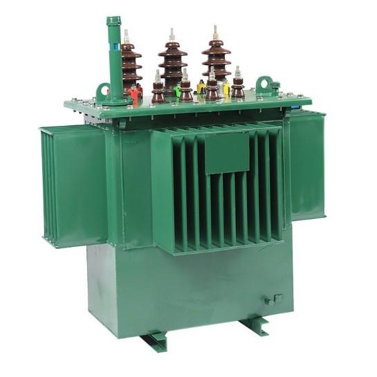
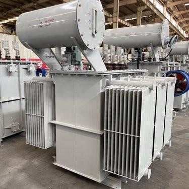
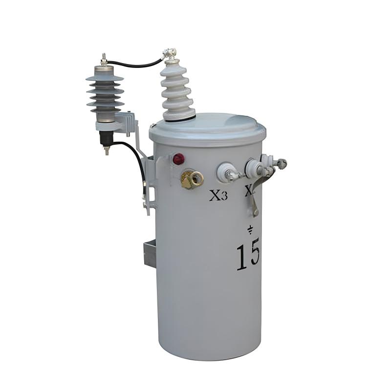
In complexo agro distributionis electricitatis, transformatores distributionis partem maximam ludunt. Hi transformatores ad gradum deprimendi tensionem a nive primaria distributionis ad tensiones utilitatis convenientes pro usuatoribus finitis destinantur. Eorum recta functio est necessaria ad stabilitatem et efficientiam rete electricitatis conservandam. Hoc articulus in duos aspectos essentiales evaluationis transformerum distributionis penetrat: probationem performance thermicae et probationem performance mechanicae, simulque explorat quomodo interpellationes servitorum praevertere et variationes tensionis administrare possimus.
Probatio Performance Thermicae Transformerum Distributionis
Significatio Inspectionis Thermicae
Transformerum distributionis calorem in operatione generant. Calor principaliter ex perdendis in windings et hysteresi core intra hos transformatores oritur. Accumulatio caloris intransformatoribus non controlata ad degradandum insulamentum, accelerandum processum senectutis transformatorum, et significativum periculum catastropharum ducere potest. Itaque inspectiones thermicae regularis transformatorum summae sunt. Haec inspectiones, quae includunt monitoring temperaturem et detectionem hotspots in transformatoribus, ut systemata praemonitionis funguntur. Cognoscendo anomalias thermicas in transformatoribus prompte, technici posse praeventuros casus et certificare deliverym continuam per rete distributionis possunt.
Componentes Principales Probationum Thermicarum pro Transformatoribus
Plures testes formam basis inspectionum performance thermicae pro transformatoribus distributionis:
Test Temperature Rise: Hoc fundamentale inspectio pro transformatoribus, hic test mensurat incrementum temperaturem in winding et oleo transformatorum sub onere ratito. Deviationes a normis stabilitis in transformatoribus signa potentialia problemata sicut inefficax refrigeratio vel problemata resistenciae internae indicant. Tales inventa proximam inspectionem componentum sicut fans refrigerantes, pinnas, vel niveles coolantium in transformatoribus provocant.
Inspection Thermal Imaging: Cameris infrared his non-invasivis inspectio pro transformatoribus employatur. Illae mappant temperatures superficiales transformatorum, ponentes lucem in hidden hotspots, quae fortasse propter conexiones laxas vel ductus obstructos intra transformatoribus oriuntur. Hoc permittit reparanda targeta in transformatoribus antequam insulamentum laedatur.
Analysis Oil Temperature: Sampling et testando viscositatem et contentum acidum olei transformatoris dat insight in stress levels thermicos experiens transformator. Elevatum aciditatem in oleo transformatoris indicat calefactionem excessivam, incitans inspectionem fontium caloris et mechanismorum refrigerationis intra transformator.
Protocolla et Standardes Inspectionum pro Transformatoribus
Standardes sicut IEEE C57.12.90 et IEC 60076 mandant systematicas inspectiones thermicas transformatorum. In testing, technici simulare conditiones full-load in transformatoribus dum stricto monitorant gradientes temperature. Sicut exempli gratia, inspectio temperature rise in transformatoribus requirit stabilizare transformatoribus per horas varias ante recording readings. Documentatio detallata cuiusque inspectionis transformatorum, includens conditions ambientes, durationes test, et profiles thermicos, facilitat analysis trend transformatorum per tempus.
Frequenta et Strategias Adaptivas pro Inspectionibus Transformatorum
Frequenta inspectionum thermicarum pro transformatoribus variat secundum varios factores sicut variabilitas oneris et conditiones ambientales. Distributiones transformatorum in urbibus cum fluctuantibus oneribus mensuales inspections requirere possunt, dum illae in ruralibus regionibus sufficiant cum quarterlies checks. In climes calidos, intervallis inter inspectiones thermicas transformatorum breviantur ad effectus stress caloris contrari. Systemata monitoring advanced nunc permittunt inspectiones thermicas continuas transformatorum per sensors embedded, qui transmittunt data real-time ab transformatoribus ad centra controlis.
Superando Difficultates Inspectionum in Transformatoribus
Inspectiones thermicae transformatorum quaedam difficultates obviant. Notabiliter, falsi positivi occurrere possunt propter spikes oneris transientes in transformatoribus. Ad hoc mitigandum, technici correlant data thermica cum parametris electricis, sicut currents oneris in transformatoribus. Praeterea, accessus ad componentes difficile attingibiles, sicut windings internos in transformatoribus, expertiam specializatam postulat. Quaedam inspectiones transformatorum requirunt draining olei, necessitantes strictam observantiam protocollos safety meticulous. Calibration regularis sensorum thermicorum in transformatoribus certificat resultatas inspectionum accuratos.
Integrando Inspectionem Thermicam cum Maintenance Transformatorum
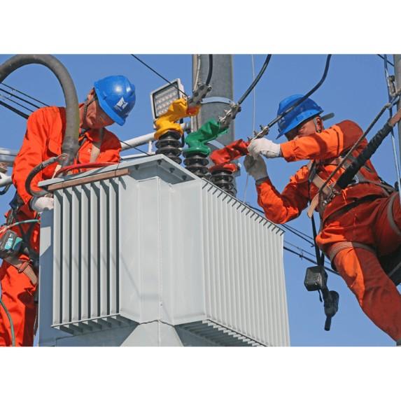
Inspectiones thermicae transformatorum servunt ut pontifex inter collectionem datarum et actiones maintenance. Report inspectio comprehensiva transformatorum, quae signa hotspots, inefficaciae refrigerationis, vel degradationis olei in transformatoribus, guidant interventiones immediatas. Sicut exempli gratia, si inspectio thermal imaging revelat cooling fin blocked in transformator, cleaning vel replacement fit prioritas. Implantando inspectiones thermicas in schedules maintenance preventivae transformatorum, operators posse extender lifespans transformatorum et reducere vulnerabilitates rete.
Probatio Performance Mechanicae Transformerum Distributionis
Indispensabilitas Inspectionis Mechanicae pro Transformatoribus
Distributiones transformatorum exposuntur ad stresses mechanicos per totum lifecycle. Faults electrici possunt generare vires electromagneticas intensas quae possunt distordere windings transformatorum. Praeterea, activitas seismica vel tractatio aspera in transportatione possunt laedere componentes internos transformatorum. Inspections mechanicus regularis, a visualibus checks ad dynamic testing transformatorum, essentialis sunt ad detectandum latentia defecta. Cognoscendo infirmitates mechanicas early in transformatoribus, operators possunt tueri contra casus subitaneos quae possint interrumpere supplym power et periclitare infrastructura tota reliantem in istis transformatoribus.
Componentes Principales Testing Mechanicus pro Transformatoribus
Plures testes integralis sunt ad inspectiones performance mechanicus pro transformatoribus distributionis:
Short-Circuit Impulse Test: Hic inspectio simulat conditiones fault ut evaluet ability transformatorum ad sustinendum vires electromagneticas. Deviationes in impedanciam vel displacement windings in transformatoribus signal mechanical stress, incitans inspectionem structurarum clamping et support frames intra transformatoribus.
Vibration Analysis Inspection: Sensors utuntur ad monitorandas vibrationes in operatione transformatorum. Frequencies abnormal detected in transformatoribus indicant problemata sicut partes laxas, cores misaligned, vel fans refrigerantes laesi. Hic methodus inspectionis non-invasivus auxiliatur technicis ad pinpointing et rectificationem problematum mechanicorum in transformatoribus antequam ipsa crescant.
Mechanical Impact Test: Applicatus in processu manufacturae vel post transportationem transformatorum, hic test evaluat resilienciam transformatorum ad shocks. Drop tests vel seismic simulations revelant vulnerabilitates in componentes sicut tank, bushings, vel terminal connections transformatorum, incitantes inspectiones junctorum criticorum.
Protocolla et Standardes Inspectionum pro Transformatoribus
Standardes sicut IEEE C57.12.90 et IEC 61378 mandant rigidas inspectiones mechanicus transformatorum. In testing, technici sequuntur procedures precisas. Sicut exempli gratia, short-circuit tests in transformatoribus requirunt injectiones currentis controlled dum stricto monitorant responses mechanicas transformatorum. Documentatio detallata cuiusque inspectionis transformatorum, includens parameters test, deformationes observatas, et recommendations repair, build record historica pro analysis futura transformatorum.
Frequenta et Adaptatio Contextualis pro Inspectionibus Transformatorum
Frequenta inspectionum mechanicarum pro transformatoribus variat secundum scenarios usus. Distributiones transformatorum in regionibus prone to earthquakes possunt subire quarterly vibration inspections, dum illae in environments stabilibus sufficiant cum annual checks. Noviter installati transformatoribus saepe recipiunt immediate post-transport inspections ad verificandum integritatem suam. Systemata monitoring advanced nunc permittunt inspectiones mechanicas continuas transformatorum per embedded strain gauges et accelerometers.
Superando Difficultates Inspectionum in Transformatoribus
Inspectiones mechanicas transformatorum sua propria complexitates habent. Detectando damnum internum sine disassembly transformatorum est obstaculum significativum. Quaedam inspectiones, sicut ultrasonic testing pro hidden cracks in transformatoribus, expertiam specializatam requirunt. Praeterea, differentiating normal wear a abnormal degradation in transformatoribus experientiam postulat. Ad haec difficultates solvendas, technici combinant plures methodos inspectionis, sicut vibration analysis cum visual inspections, et leverant data historica pro comparative assessments transformatorum.
Integrando Inspectionem Mechanicam cum Maintenance Transformatorum
Inspectiones mechanicas transformatorum servunt ut nexus crucialis inter diagnosin et actionem. Report inspectionis comprehensiva transformatorum, quae signa problemata sicut loose bolts, deformed windings, vel compromised supports, dictat urgent repairs vel replacementes componentum. Sicut exempli gratia, si inspectio vibrationis revelat core misaligned in transformator, realignment et retightening fit top priorities. Implantando inspectiones mechanicas in schedules maintenance preventivae transformatorum, operators posse extender lifespans transformatorum et fortify grid resilience.
Preventing an Interruption of Service in Distribution Transformers
How Transformers, Secondaries, and Fuses Operate
Transformerum distributionis step down voltage a distributione vel primary feeder voltage ad utilization voltage. Ipsi connectuntur ad primary feeder, sub-feeders, et laterals per primary fuses vel fused cutouts. Primary fuse disconnects suum associatum distributionem transformatoris a primary feeder quando fault transformatoris vel low-impedance secondary-circuit fault occurrit. Fused cutouts, quae normaliter clausae sunt, provide convenient means for disconnecting small distribution transformers for inspection and maintenance.
Satisfactory overload protection of a distribution transformer cannot be achieved with a primary fuse alone. This is due to the difference in the shape of its current-time curve and the safe current-time curve of a distribution transformer. If a small enough fuse is used to offer complete overload protection for the transformer, much of the valuable transformer overload capacity is lost as the fuse blows prematurely. Such a small fuse also frequently blows unnecessarily on surge currents. Therefore, a primary fuse should be selected based on providing short-circuit protection only, with its minimum blowing current usually exceeding 200% of the full load current of its associated transformer.
Distribution transformers connected to overhead open-wire feeders are often subjected to severe lightning disturbances. To minimize insulation breakdown and transformer failures from lightning, lightning arresters are commonly used with these transformers.
The secondary leads of a distribution transformer are typically solidly connected to radial secondary circuits, from which consumer services are tapped. This means that the transformer lacks protection against overloads and high-impedance faults on its secondary circuits. Relatively few distribution transformers are burned out by overloads, mainly because they are often not fully utilized to their overload capacity. Another factor contributing to the low number of overload-related failures is the frequent load checks and corrective measures taken before dangerous overloads occur. However, high impedance faults on their secondary circuits likely cause more distribution transformer failures than overloads, especially in areas with poor tree conditions.
Fuses in the secondary leads of distribution transformers are little more effective in preventing transformer burnouts than primary fuses, for similar reasons. The proper way to obtain satisfactory protection for a distribution transformer against overloads and high-impedance faults is by installing a circuit breaker in the secondary leads of the transformer. The tripping curve of this circuit breaker must be properly coordinated with the safe current-time curve of the transformer. The primary fuse must also be coordinated with the secondary breaker so that the breaker trips on any current that can pass through it before the fuse is damaged.
Faults on a consumer’s service connection from the secondary circuit to the service switch are extremely rare. Thus, the use of a secondary fuse at the point where the service connection taps onto the secondary circuit is not economically justifiable, except in unusual cases such as large services from underground secondaries.
Voltage Variation Considerations
Assuming a maximum voltage variation of about 10% at any consumer’s service switch, the division of this drop among the various parts of the system, at full load, may be approximately as follows:
2% voltage variation in the primary feeder between the first and last transformers
2.5% voltage variation in the distribution transformer
3% voltage variation in the secondary circuit
0.5% voltage variation in the consumer’s service connection
The fact that the voltage at the primary of the first distribution transformer cannot ordinarily be maintained exactly accounts for the other 2%.
These figures are typical for overhead systems supplying residential loads. However, they can be expected to differ significantly in underground systems where cable circuits and large distribution transformers are used, or when supplying industrial and commercial loads.
The economic size of the distribution transformer and secondary-circuit combination for any uniform load density and type of construction, at specific market prices, can be readily determined once the total allowable voltage drop in these two parts of the system is established. If the transformer is too large, the secondary circuit cost and total cost will be excessive. Conversely, if the transformer is too small, the transformer cost and total cost will be too high.
Handling Load Changes in Transformers
As in any other part of the distribution system, load change or load growth must be considered and planned for in distribution transformers and secondary circuits. Distribution transformers and secondary circuits are not installed merely to serve the loads existing at the time of installation but also to accommodate some future loads. However, it is not economical to make excessive allowance for growth.
When a distribution transformer becomes dangerously overloaded, it can be replaced by one of the next larger size if the current-carrying capacity of the secondary circuit and the overall voltage regulation permit. If not, another transformer of about the same size can be installed between the overloaded transformer and the adjacent one. This involves removing load from the overloaded transformer by connecting part of its secondary circuit and associated load to the new transformer. This also reduces the load on the secondary circuit of the overloaded transformer and improves the overall voltage regulation. In areas with reasonably uniform load, transformers may need to be installed on both sides of the overloaded transformer relatively quickly to maintain satisfactory voltage conditions and prevent overloading parts of the secondary circuit. The same result can also be achieved by installing one new transformer and relocating the overloaded transformer so that it feeds into the center of its shortened secondary circuit.
Transformer Banking for Service Improvement
With distribution transformers and secondary circuits arranged as in the typical radial configuration, any one load is supplied through only one transformer and in only one direction over the secondary circuit. Because of this, a suddenly applied load, such as when starting a motor, on a consumer’s service can cause objectionable light flicker on other consumers’ services fed from the same transformer. The increasing use of motor-driven appliances in residential areas is resulting in a significant number of light-flicker complaints. In some areas, light flicker, rather than voltage regulation, may be the determining factor in the size and arrangement of transformers and secondary circuits.
The banking of distribution transformers is usually the best and most economical means of improving or eliminating light flicker. Banking transformers means paralleling on the secondary side a number of transformers all connected to the same primary circuit. The secondary circuit arrangement in a banked transformer layout can take various forms, such as loops or grids similar to those used in a secondary network system. However, banked transformers, being connected to and supplied over a single radial-primary feeder, are a form of radial distribution system, unlike a secondary network loop or grid which is supplied over two or more primary feeders and offers much greater service reliability.
The conversion from the usual radial secondary circuit arrangement to the banked-transformer arrangement can usually be done simply and cheaply by closing the gaps between the radial secondaries of a number of transformers associated with the same primary feeder and installing the proper primary and secondary fuses.
Protection in Transformer Banking
Two major forms of protection have been used when banking distribution transformers. The first arrangement, which is probably the oldest and most common, involves connecting the distribution transformers to the primary feeder through primary fuses or fused cutouts. These fuses should blow only on a fault in their associated transformer. All transformers are connected to the common secondary circuit through secondary fuses, whose purpose is to disconnect a faulty transformer from the secondary circuit. The size of the secondary fuse must be such that it will blow on a primary fault between its transformer and the associated primary fuse. Faults on the secondary circuit are normally expected to burn themselves clear. To prevent frequent blowing of secondary fuses on secondary-circuit faults, these fuses should have relatively long blowing times on all fault currents, but not so long as to fail to provide some protection to the transformers against secondary faults that do not clear quickly.
Using a secondary breaker with proper current-time characteristics is preferable to secondary fuses when banking transformers as it offers greater protection to the transformer against overloads and high-impedance faults. The secondary fuses or breakers should open in less time than the primary fuses on any possible current to prevent the blowing of primary fuses on a secondary fault.
A transformer fault is cleared by the transformer’s primary and secondary fuses without interrupting service. Most secondary faults clear quickly, but when a secondary fault persists, several or all of the secondary fuses may blow and some transformers may be burned out. Experience shows that with careful study of expected fault currents and proper selection of primary and secondary fuses, this method of banking operates with minimal issues. However, occasionally a secondary-circuit fault causes multiple secondary fuses to blow and some transformers to burn out, resulting in a greater service interruption than with radial secondary circuits.
The second transformer banking arrangement is preferable as there is no danger of a complete service interruption to the banked area due to a secondary fault. In this arrangement, distribution transformers are connected to the primary feeder through primary fuses for the same reasons as in the first arrangement. The transformers are solidly connected to the secondary circuit, which is sectionalized between transformers by secondary fuses. These fuses are selected to blow quicker than any primary fuse for any secondary-circuit fault. When a transformer fails, it is removed from the system by its primary fuse and the adjacent secondary fuses on either side. Thus, a transformer fault results in a service interruption only for the consumers associated with the faulty transformer. A secondary-circuit fault usually burns clear, but if it persists, it is cleared by the secondary fuses next to the faulty section and the primary fuse of the associated transformer. The secondary fuses are typically selected to operate even on high-impedance faults, while the primary fuses are not, for the reasons discussed earlier regarding radial-secondary circuits. This ensures that even with a persistent high-impedance fault, the adjacent secondary fuses blow and prevent service interruption on the unaffected secondary sections, although the associated transformer may be burned out. To prevent this, a secondary breaker with a current-time curve coordinated with the safe current-time curve of the transformer can be used in the secondary leads of the transformer. When such a breaker is used, the secondary fuses must be selected so that their blowing times for all fault currents are less than the tripping times of the breakers.
Normally, the two banking arrangements function similarly. They reduce or eliminate light flicker and improve voltage regulation or allow for a reduction in the amount of transformer capacity required compared to radial-secondary circuits. This improvement is due to tying several radial-secondary circuits together and taking advantage of the diversity among different consumer groups. A significant increase in the use of banked transformers can be expected in the future, as these advantages can often be achieved at no additional cost or with a saving compared to the usual radial secondary-circuit arrangement.
In conclusion, both thermal and mechanical performance testing of distribution transformers are crucial for maintaining the reliability and longevity of these essential components in the power distribution system. By understanding their operational characteristics, implementing proper inspection and protection measures, and addressing issues such as voltage variation and load growth, we can ensure a stable and efficient power supply for consumers.


