Johdanto
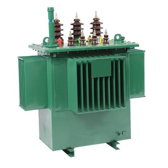
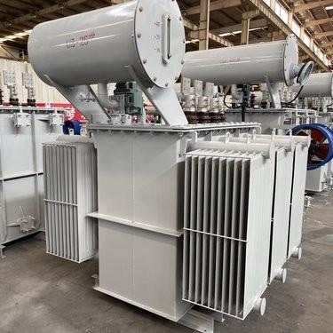
Monimutkaisessa sähköjakelun maailmassa jakamustransformatorit ovat keskeisessä roolissa. Nämä transformatorit tehtävänään alentaa jännitteitä pääjakelutasosta sopivaan käyttöjännitteeseen loppukäyttäjille. Niiden asianmukainen toiminta on välttämätöntä vakauden ja tehokkuuden ylläpitämiseksi sähköverkossa. Tässä artikkelissa tarkastellaan kahden tärkeän näkökulman jakamustransformatorien arvioinnissa: lämpösuorituskyksen testaus ja mekaanisen suorituskyksen testaus, sekä palstaillaan myös palveluhäiriöiden estoa ja jännitevaihtelujen hallintaa.
Jakamustransformatorien lämpösuorituskyksen testaus
Lämpöinspektion merkitys
Jakamustransformatorit tuottavat lämpöä toiminnassaan. Lämpö syntyy pääasiassa kytkentöjen ja ytimen hystereettisten häviöiden vuoksi näissä transformaattoreissa. Kontrollin ulkopuolella olevan lämpöenergian kasautuminen transformaattoreissa voi johtaa eristysaineen heikkenemiseen, nopeuttaa transformaattorien ikääntymistä ja aiheuttaa merkittävän riskin katastrofaaliselle sijaisuudelle. Säännölliset lämpöinspektiot transformaattoreissa ovat siksi äärimmäisen tärkeitä. Nämä inspektiot, jotka sisältävät lämpötilan valvonnan ja kuumen pisteen havaitsemisen transformaattoreissa, toimivat varoitusjärjestelmänä. Lämpöpoikkeamien tunnistaminen transformaattoreissa heti mahdollisuuksien mukaan auttaa teknisiä henkilöstöä ennaltaehkäisemään sijaisuuksia ja varmistamaan keskeytymättömän sähköjakelun verkostossa.
Tärkeimmät lämpötestauskomponentit transformaattoreille
Useat testit muodostavat perustan lämpösuorituskyksen inspektioille jakamustransformatorissa:
Lämpötilan nousutesti: Tämä on perustesti transformaattoreille, joka mitataan kytkentöjen ja öljyn lämpötilan nousua transformaattoreissa suunnitellulla kuormituksella. Poikkeamat asetetuista standardeista transformaattoreissa viittaavat mahdollisiin ongelmiin, kuten tehottomaan jähdytykseen tai sisäisiin vastusongelmiin. Tällaiset löydökset vaativat lähemmäs tutkimusta komponenteista, kuten jähdytysventtiileistä, levistä tai jähdytysvälineiden tasosta transformaattoreissa.
Termografinen inspektio: Infrapunasovellukset käytetään tähän ei-invaasiviseen inspektiomenetelmään transformaattoreissa. Ne karttaavat transformaattoreiden pinnan lämpötilat, korostamalla piilossa olevia kuumeisia kohtia, jotka voivat johtua löysistä yhteyksistä tai tukkuneista kanavista transformaattoreissa. Tämä mahdollistaa kohdennetut korjaukset transformaattoreissa ennen eristysaineen vaurioitumista.
Öljylämpötilan analyysi: Öljyn viskositeetin ja happamuuden otantatestaus tarjoaa tietoa transformaattoreiden kokemasta lämpöstressistä. Korkea happamuus öljyssä transformaattoreissa viittaa liialliseen lämmittymiseen, mikä aktivoi lähteiden ja jähdytysmekanismien tutkimuksen transformaattoreissa.
Inspektion protokollat ja standardit transformaattoreille
IEEE C57.12.90 ja IEC 60076 -standardit määräävät järjestelmällisiä lämpöinspektioita transformaattoreille. Testauksessa teknisiä simuloivat täysi kuormitus transformaattoreissa samalla kun he seuraavat lämpötilagradientteja. Esimerkiksi lämpötilan nousutestissä transformaattoreissa on vakaistettava useita tunteja ennen lukemusten ottamista. Jokaisen inspektion yksityiskohtainen dokumentointi, mukaan lukien ympäristöolosuhteet, testausteknologiat ja lämpöprofiilit, edistää trendianalyysiä transformaattoreissa ajan myötä.
Transformaattorien inspektioiden taajuus ja sopeutettavat strategiat
Lämpöinspektioiden taajuus transformaattoreille riippuu monista tekijöistä, kuten kuorman vaihtelu ja ympäristöolosuhteet. Kaupunkialueilla sijaitsevat jakamustransformatorit, joilla on vaihteleva kuormitus, saattavat vaatia kuukausittaisia inspektionia, kun taas maaseudulla sijaitseville transformaattoreille voi riittää neljänneksittäiset tarkastukset. Kuivalmissa ilmastossa lämpöinspektioiden väli transformaattoreissa lyhenee vastustaakseen lämpöstressin vaikutuksia. Edistyneet valvontajärjestelmät mahdollistavat nyt jatkuvan lämpöinspektion transformaattoreissa upotettujen anturien avulla, jotka välittävät reaaliaikaista dataa transformaattoreista ohjauskeskuksiin.
Inspektion haasteiden ylittäminen transformaattoreissa
Lämpöinspektioiden transformaattoreissa kohtaavat tietyt haasteet. Erityisesti väliaikaiset kuormituspiikit transformaattoreissa voivat aiheuttaa epävarmoja positiivisia tuloksia. Vähentääkseen tätä teknisiä yhdistävät lämpödatan sähköisiin parametreihin, kuten kuormitusvirtauksiin transformaattoreissa. Lisäksi vaikeasti saatavilla olevien komponenttien, kuten sisäisten kytkentöjen, transformaattoreissa pääsy vaatii erikoistunutta osaamista. Joissakin inspektioissa transformaattoreissa on tarpeen tyhjentää öljy, mikä vaatii tarkkanäköisen turvallisuusprotokollien noudattamisen. Transformaattoreiden lämpöanturien säännöllinen kalibrointi takaa tarkat inspektion tulokset.
Lämpöinspektion integrointi transformaattorien huoltoon
Lämpöinspektioiden transformaattoreissa toimii silta datan keräämiseen ja huoltotoimiin. Kattavan inspektion raportti, joka lippaisee kuumeiset kohdat, jähdytystehottomuudet tai öljyn rappeutumisen transformaattoreissa, ohjaa välittömiä toimia. Esimerkiksi jos termografinen inspektio paljastaa tukkuneen jähdytyslevyn transformaattoriin, siivous tai korvaaminen tulee ensisijaiseksi. Upotettujen lämpöinspektioiden huoltosuunnitelmiin transformaattoreissa operaatiorit voivat pidentää transformaattorien käyttöikää ja vähentää verkon haavoittuvuutta.
Jakamustransformatorien mekaanisen suorituskyvyn testaus
Mekaanisen inspektion välttämättömyys transformaattoreille
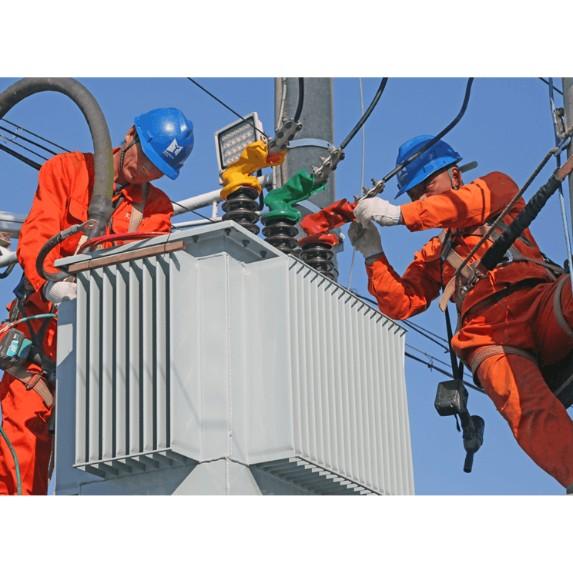
Jakamustransformatorit altistuvat mekaaniselle stressille koko elinkaikkansa ajan. Sähköiset sijaisuudet voivat tuottaa voimakkaita sähkömagneettisia voimia, jotka voivat vääntää transformaattorien kytkentöjä. Lisäksi maanjäristykset tai karu käsitteleminen kuljetuksen aikana voivat vahingoittaa transformaattorien sisäisiä komponentteja. Säännölliset mekaaniset inspektiot, jotka ulottuvat visuaalisista tarkastuksista dynaattisiin testeihin transformaattoreissa, ovat välttämättömiä piilossa olevien puutteiden havaitsemiseksi. Mekaanisten heikkouksien tunnistaminen ajoissa transformaattoreissa mahdollistaa operaattoreiden suojelemisen yhtäkkiä tapahtuvalta sijaisuudelta, joka voisi häiritä sähköntarjontaa ja vaarantaa koko infrastruktuurin, joka on riippuvainen näistä transformaattoreista.
Ydinmekaaniset testauskomponentit transformaattoreille
Useat testit ovat olennaisia jakamustransformatorien mekaanisen suorituskyvyn inspektionille:
Lyhytsirunpuristusimpulsitesti: Tämä inspektio simuloi sijaisuustilanteita arvioidakseen transformaattorien kykyä kestää sähkömagneettisia voimia. Impedanssin tai kytkentöjen siirtymisen poikkeamat transformaattoreissa viittaavat mekaaniseen stressiin, mikä aktivoi puristusmekanismien ja tukikehyksien inspektion transformaattoreissa.
Värinäanalyysin inspektio: Antureita käytetään värinän valvomiseen transformaattorien toiminnan aikana. Epänormaalit taajuudet, jotka havaitaan transformaattoreissa, viittaavat ongelmiin, kuten löyhkäisiin osiin, väärästi kohdistettuihin ytimeen tai vaurioituihin jähdytysventtiileihin. Tämä ei-invaasivinen inspektiomuoto auttaa teknisiä paikallistamaan ja korjaamaan mekaanisia ongelmia transformaattoreissa ennen kuin ne pahenevat.
Mekaaninen vaikutustesti: Sovitettu valmistusprosessin aikana tai transformaattorien kuljetuksen jälkeen, tämä testi arvioi transformaattorien resilienssiä iskuille. Putoamistestit tai maanjäristys-simulaatiot paljastavat haavoittuvuudet komponenteissa, kuten säiliössä, sokkeissa tai terminaaliyhteyksissä transformaattoreissa, mikä aktivoi kriittisten yhtymien inspektion.
Inspektion protokollat ja standardit transformaattoreille
IEEE C57.12.90 ja IEC 61378 -standardit määräävät tiukkoja mekaanisia inspektioita transformaattoreille. Testauksessa teknisiä noudattavat tarkkoja menettelytapoja. Esimerkiksi lyhytsirunpuristustestit transformaattoreissa vaativat kontrolloituja virtasuuntia samalla kun he seuraavat tarkasti transformaattorien mekaanisia reaktioita. Jokaisen inspektion yksityiskohtainen dokumentointi, mukaan lukien testiparametrit, havaitut muodonmuutokset ja korjausluonnokset, rakentaa historiallisen ennakkotiedon tulevan analyysin transformaattoreissa.
Mekaanisten inspektioiden taajuus ja kontekstuaalinen sopeutus transformaattoreille
Mekaanisten inspektioiden taajuus transformaattoreille vaihtelee käyttötarkoitusten mukaan. Jakamustransformatorit maanjäristysaltisilla alueilla voivat suorittaa kvartaalittaisia värinäinspektioita, kun taas vakaiden ympäristöjen transformaattorit voivat riittää vuosittaisilla tarkastuksilla. Uudet transformaattorit saattavat saada välittömät post-kuljetusinspektiot vahvistaakseen niiden eheyden. Edistyneet valvontajärjestelmät mahdollistavat nyt jatkuvan mekaanisen inspektion transformaottoreissa upotettujen venymismittarien ja kiihtyvyysmittarien avulla.
Inspektion haasteiden ylittäminen transformaattoreissa
Mekaanisten inspektioiden transformaattoreissa on omia monimutkaisuuksiaan. Sisäisten vaurioiden havaitseminen ilman, että transformaattorit puretaan, on merkittävä este. Joissakin inspektionissa, kuten ultraviolettitekniikan käyttö piilossa olevien rakoisten havaitsemiseksi transformaattoreissa, vaaditaan erikoistunutta osaamista. Lisäksi normaalin kulun ja epänormaalin rappeutumisen erottaminen transformaattoreissa vaatii kokemusta. Näiden haasteiden ratkaisemiseksi teknisiä yhdistävät useita inspektion menetelmiä, kuten värinäanalyysin visuaalisiin tarkastuksiin, ja hyödyntävät historiallista dataa vertailevia arviointeja transformaattoreissa.
Mekaanisen inspektion integrointi transformaattorien huoltoon
Mekaaniset inspektiot transformaattoreissa toimivat välttämättömänä linkkinä diagnoosiin ja toimiin. Kattavan inspektion raportti, joka lippaisee ongelmat, kuten löydet pultit, vääntyneet kytkentät tai heikentyneet tukirakenteet, määrää kiireellisiä korjauksia tai komponenttien korvaamista. Esimerkiksi, jos värinäinspektio paljastaa väärästi kohdistetun ytimen transformaattoriin, uudelleenasettelu ja uudelleenkiinnitys tulevat etusijalle. Upotettujen mekaanisten inspektioiden huoltosuunnitelmiin transformaattoreissa operaattorit voivat pidentää transformaattorien käyttöikää ja vahvistaa verkon resilienssiä.
Jakamustransformatorien palveluhäiriön estäminen
Kuinka transformaattorit, toissijaiset ja fuusit toimivat
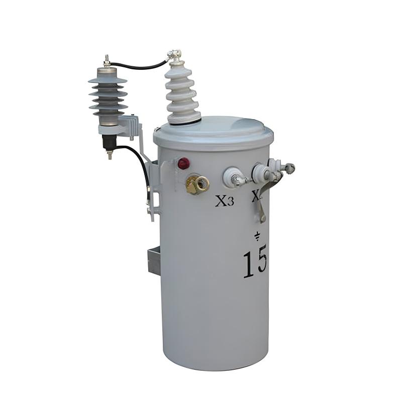
Jakamustransformatorit laskevat jännitettä jakelutasosta tai päävoimalajänteestä käyttöjännitteeseen. Ne yhdistetään päävoimalajänteeseen, sub-feederiin ja sivuruteihin pääfuusien tai fuusiokatkaisijoiden kautta. Pääfuse katkaisee sen mukanaan kulkevan jakamustransformatorin päävoimalajänteestä, kun transformaattorisijaisuus tai matala impedanssin toissijainen sijaisuus tapahtuu. Fuusiokatkaisijat, jotka ovat tavallisesti suljettuja, tarjoavat kätevän keinon irrottaa pieniä jakamustransformatoreita tarkastusta ja huoltoa varten.
Satisfactory overload protection of a distribution transformer cannot be achieved with a primary fuse alone. This is due to the difference in the shape of its current-time curve and the safe current-time curve of a distribution transformer. If a small enough fuse is used to offer complete overload protection for the transformer, much of the valuable transformer overload capacity is lost as the fuse blows prematurely. Such a small fuse also frequently blows unnecessarily on surge currents. Therefore, a primary fuse should be selected based on providing short-circuit protection only, with its minimum blowing current usually exceeding 200% of the full load current of its associated transformer.
Distribution transformers connected to overhead open-wire feeders are often subjected to severe lightning disturbances. To minimize insulation breakdown and transformer failures from lightning, lightning arresters are commonly used with these transformers.
The secondary leads of a distribution transformer are typically solidly connected to radial secondary circuits, from which consumer services are tapped. This means that the transformer lacks protection against overloads and high-impedance faults on its secondary circuits. Relatively few distribution transformers are burned out by overloads, mainly because they are often not fully utilized to their overload capacity. Another factor contributing to the low number of overload-related failures is the frequent load checks and corrective measures taken before dangerous overloads occur. However, high impedance faults on their secondary circuits likely cause more distribution transformer failures than overloads, especially in areas with poor tree conditions.
Fuses in the secondary leads of distribution transformers are little more effective in preventing transformer burnouts than primary fuses, for similar reasons. The proper way to obtain satisfactory protection for a distribution transformer against overloads and high-impedance faults is by installing a circuit breaker in the secondary leads of the transformer. The tripping curve of this circuit breaker must be properly coordinated with the safe current-time curve of the transformer. The primary fuse must also be coordinated with the secondary breaker so that the breaker trips on any current that can pass through it before the fuse is damaged.
Faults on a consumer’s service connection from the secondary circuit to the service switch are extremely rare. Thus, the use of a secondary fuse at the point where the service connection taps onto the secondary circuit is not economically justifiable, except in unusual cases such as large services from underground secondaries.
Voltage Variation Considerations
Assuming a maximum voltage variation of about 10% at any consumer’s service switch, the division of this drop among the various parts of the system, at full load, may be approximately as follows:
2% voltage variation in the primary feeder between the first and last transformers
2.5% voltage variation in the distribution transformer
3% voltage variation in the secondary circuit
0.5% voltage variation in the consumer’s service connection
The fact that the voltage at the primary of the first distribution transformer cannot ordinarily be maintained exactly accounts for the other 2%.
These figures are typical for overhead systems supplying residential loads. However, they can be expected to differ significantly in underground systems where cable circuits and large distribution transformers are used, or when supplying industrial and commercial loads.
The economic size of the distribution transformer and secondary-circuit combination for any uniform load density and type of construction, at specific market prices, can be readily determined once the total allowable voltage drop in these two parts of the system is established. If the transformer is too large, the secondary circuit cost and total cost will be excessive. Conversely, if the transformer is too small, the transformer cost and total cost will be too high.
Handling Load Changes in Transformers
As in any other part of the distribution system, load change or load growth must be considered and planned for in distribution transformers and secondary circuits. Distribution transformers and secondary circuits are not installed merely to serve the loads existing at the time of installation but also to accommodate some future loads. However, it is not economical to make excessive allowance for growth.
When a distribution transformer becomes dangerously overloaded, it can be replaced by one of the next larger size if the current-carrying capacity of the secondary circuit and the overall voltage regulation permit. If not, another transformer of about the same size can be installed between the overloaded transformer and the adjacent one. This involves removing load from the overloaded transformer by connecting part of its secondary circuit and associated load to the new transformer. This also reduces the load on the secondary circuit of the overloaded transformer and improves the overall voltage regulation. In areas with reasonably uniform load, transformers may need to be installed on both sides of the overloaded transformer relatively quickly to maintain satisfactory voltage conditions and prevent overloading parts of the secondary circuit. The same result can also be achieved by installing one new transformer and relocating the overloaded transformer so that it feeds into the center of its shortened secondary circuit.
Transformer Banking for Service Improvement
With distribution transformers and secondary circuits arranged as in the typical radial configuration, any one load is supplied through only one transformer and in only one direction over the secondary circuit. Because of this, a suddenly applied load, such as when starting a motor, on a consumer’s service can cause objectionable light flicker on other consumers’ services fed from the same transformer. The increasing use of motor-driven appliances in residential areas is resulting in a significant number of light-flicker complaints. In some areas, light flicker, rather than voltage regulation, may be the determining factor in the size and arrangement of transformers and secondary circuits.
The banking of distribution transformers is usually the best and most economical means of improving or eliminating light flicker. Banking transformers means paralleling on the secondary side a number of transformers all connected to the same primary circuit. The secondary circuit arrangement in a banked transformer layout can take various forms, such as loops or grids similar to those used in a secondary network system. However, banked transformers, being connected to and supplied over a single radial-primary feeder, are a form of radial distribution system, unlike a secondary network loop or grid which is supplied over two or more primary feeders and offers much greater service reliability.
The conversion from the usual radial secondary circuit arrangement to the banked-transformer arrangement can usually be done simply and cheaply by closing the gaps between the radial secondaries of a number of transformers associated with the same primary feeder and installing the proper primary and secondary fuses.
Protection in Transformer Banking
Two major forms of protection have been used when banking distribution transformers. The first arrangement, which is probably the oldest and most common, involves connecting the distribution transformers to the primary feeder through primary fuses or fused cutouts. These fuses should blow only on a fault in their associated transformer. All transformers are connected to the common secondary circuit through secondary fuses, whose purpose is to disconnect a faulty transformer from the secondary circuit. The size of the secondary fuse must be such that it will blow on a primary fault between its transformer and the associated primary fuse. Faults on the secondary circuit are normally expected to burn themselves clear. To prevent frequent blowing of secondary fuses on secondary-circuit faults, these fuses should have relatively long blowing times on all fault currents, but not so long as to fail to provide some protection to the transformers against secondary faults that do not clear quickly.
Using a secondary breaker with proper current-time characteristics is preferable to secondary fuses when banking transformers as it offers greater protection to the transformer against overloads and high-impedance faults. The secondary fuses or breakers should open in less time than the primary fuses on any possible current to prevent the blowing of primary fuses on a secondary fault.
A transformer fault is cleared by the transformer’s primary and secondary fuses without interrupting service. Most secondary faults clear quickly, but when a secondary fault persists, several or all of the secondary fuses may blow and some transformers may be burned out. Experience shows that with careful study of expected fault currents and proper selection of primary and secondary fuses, this method of banking operates with minimal issues. However, occasionally a secondary-circuit fault causes multiple secondary fuses to blow and some transformers to burn out, resulting in a greater service interruption than with radial secondary circuits.
The second transformer banking arrangement is preferable as there is no danger of a complete service interruption to the banked area due to a secondary fault. In this arrangement, distribution transformers are connected to the primary feeder through primary fuses for the same reasons as in the first arrangement. The transformers are solidly connected to the secondary circuit, which is sectionalized between transformers by secondary fuses. These fuses are selected to blow quicker than any primary fuse for any secondary-circuit fault. When a transformer fails, it is removed from the system by its primary fuse and the adjacent secondary fuses on either side. Thus, a transformer fault results in a service interruption only for the consumers associated with the faulty transformer. A secondary-circuit fault usually burns clear, but if it persists, it is cleared by the secondary fuses next to the faulty section and the primary fuse of the associated transformer. The secondary fuses are typically selected to operate even on high-impedance faults, while the primary fuses are not, for the reasons discussed earlier regarding radial-secondary circuits. This ensures that even with a persistent high-impedance fault, the adjacent secondary fuses blow and prevent service interruption on the unaffected secondary sections, although the associated transformer may be burned out. To prevent this, a secondary breaker with a current-time curve coordinated with the safe current-time curve of the transformer can be used in the secondary leads of the transformer. When such a breaker is used, the secondary fuses must be selected so that their blowing times for all fault currents are less than the tripping times of the breakers.
Normally, the two banking arrangements function similarly. They reduce or eliminate light flicker and improve voltage regulation or allow for a reduction in the amount of transformer capacity required compared to radial-secondary circuits. This improvement is due to tying several radial-secondary circuits together and taking advantage of the diversity among different consumer groups. A significant increase in the use of banked transformers can be expected in the future, as these advantages can often be achieved at no additional cost or with a saving compared to the usual radial secondary-circuit arrangement.
In conclusion, both thermal and mechanical performance testing of distribution transformers are crucial for maintaining the reliability and longevity of these essential components in the power distribution system. By understanding their operational characteristics, implementing proper inspection and protection measures, and addressing issues such as voltage variation and load growth, we can ensure a stable and efficient power supply for consumers.


