What is a PNP Transistor?

Encyclopedia
08/29/2024


What is a PNP Transistor?


PNP Transistor Definition


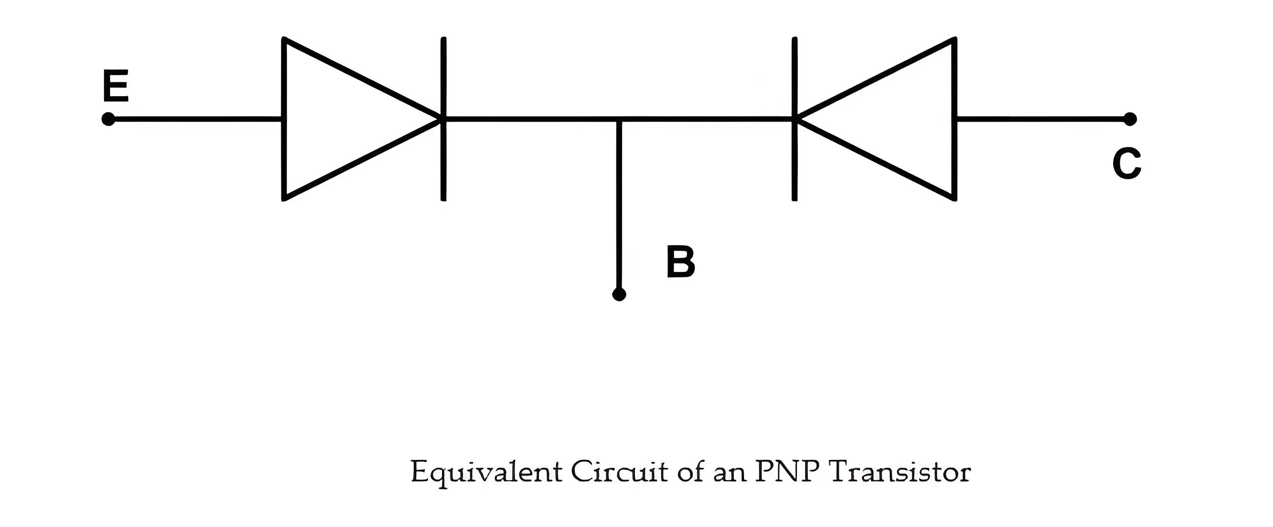
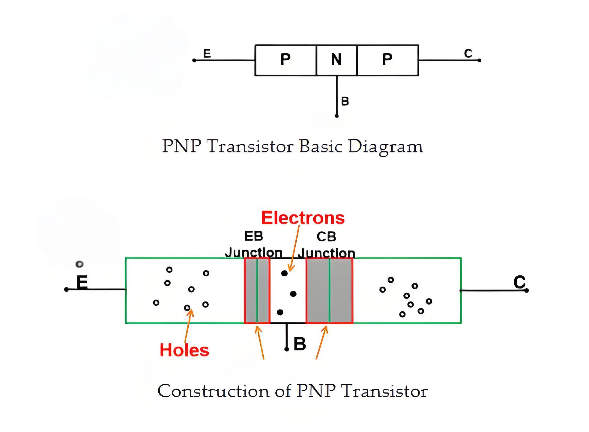
A PNP transistor is defined as a bipolar junction transistor with an N-type semiconductor sandwiched between two P-type semiconductors.


9f6775e8e9b8460c8411bb696520a7e4.jpeg


Symbol of PNP Transistor


The symbol includes an arrow on the Emitter showing the direction of conventional current flow.


24f41c7b55b1274404dd6489389b00a3.jpeg


Current Flow Direction


In a PNP transistor, the current flows from the Emitter to the Collector.


Working Principle


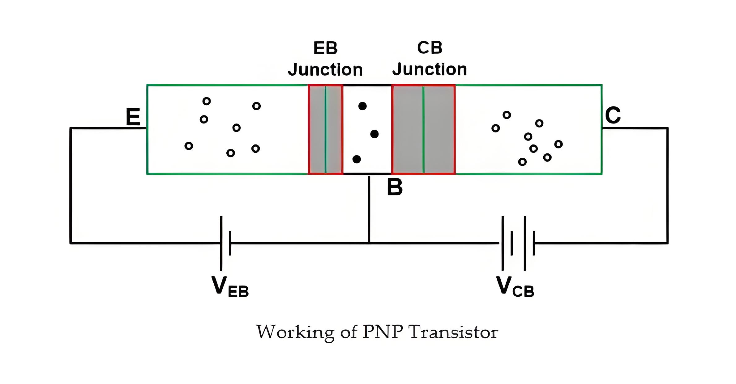
The positive terminal of a voltage source (VEB) is connected with Emitter (P-type) and the negative terminal is connected with the Base terminal (N-type). Therefore, the Emitter-Base junction is connected in forward bias.


And the positive terminal of a voltage source (VCB) is connected with the Base terminal (N-type) and the negative terminal is connected with the Collector terminal (P-type). Hence, the Collector-Base junction is connected in reverse bias.


4cabbe30a9fcd8e666ce75b747b99556.jpeg


Due to this type of bias, the depletion region at Emitter-Base junction is narrow, because it is connected in forward bias. While the Collector-Base junction is in reverse bias and hence the depletion region at Collector-Base junction is wide.


The Emitter-Base junction is forward biased, allowing many holes from the Emitter to cross into the Base. At the same time, a few electrons from the Base enter the Emitter and recombine with the holes.


The loss of holes in the emitter is equal to the number of electrons present in the Base layer. But The number of electrons in the Base is very small because it is a very lightly doped and thin region. Therefore, almost all holes of Emitter will cross the depletion region and enter into the Base layer.


Because of the movement of holes, the current will flow through the Emitter-Base junction. This current is known as Emitter current (IE). The holes are majority charge carriers to flow the Emitter current.


The remaining holes which do not recombine with electrons in Base, that holes will further travel to the Collector. The Collector current (IC) flows through the Collector-Base region due to holes.


PNP Transistor Circuit


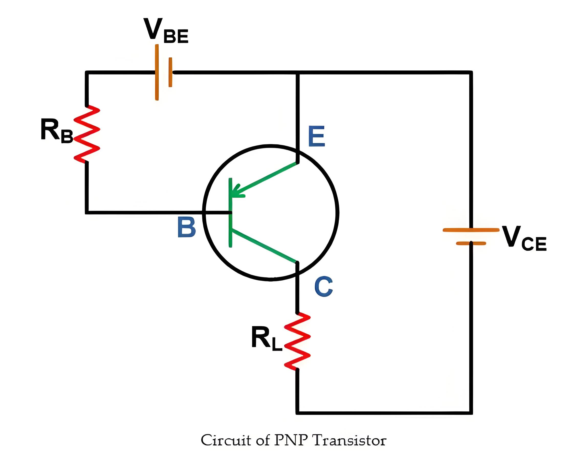
The circuit of the PNP transistor is as shown in the below figure.


6f36c27ae247ff393d0513f6c32fcca8.jpeg


If we compare the circuit of PNP transistor with NPN transistor, then here the polarity and direction of current are reversed.


If a PNP transistor is connected with voltage sources as shown in the above figure, the base current will flow through the transistor. The small amount of base current controls the flow of a large amount of current through emitter to collector provided that the Base voltage is more negative than the Emitter voltage.


If the Base voltage is not more negative than the Emitter voltage, the current cannot flow through the device. So, it is necessary to give a voltage source in reverse bias more than 0.7 V.


Two resistors RL and RB connected in the circuit to limit the maximum amount of current through the transistor.


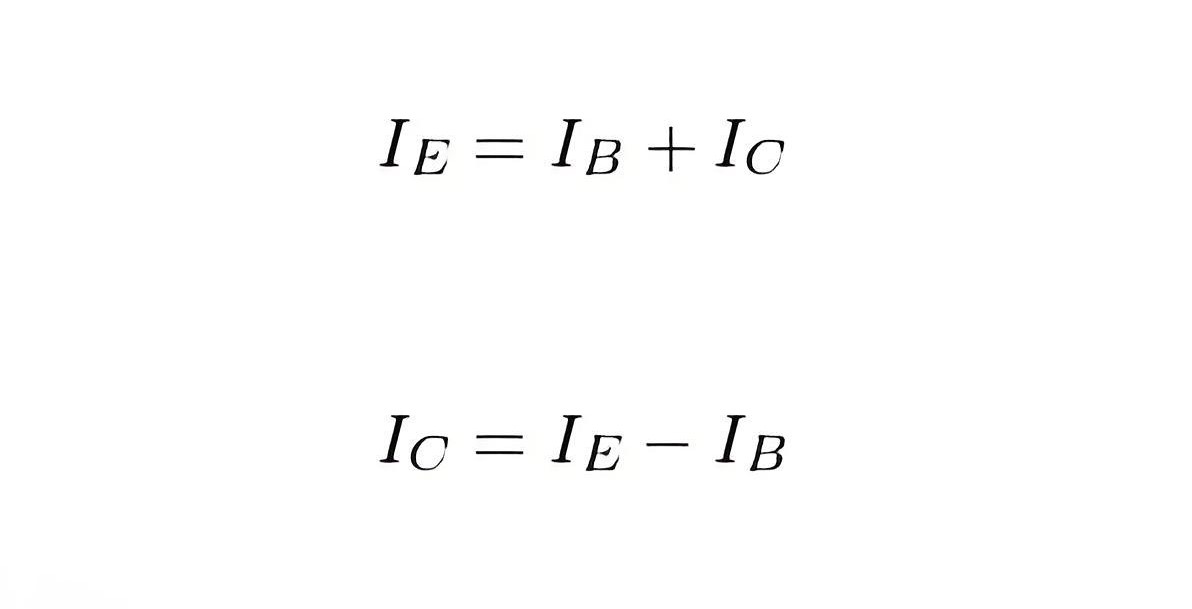
If you apply a Kirchhoff’s current law (KCL), the emitter current is a summation of the base current and collector current.


1e82131353e31920dd7f59f691d4701b.jpeg


PNP Transistor Switch


Generally, when a switch is OFF, current cannot flow, acting as an open circuit. When the switch is ON, current flows through the circuit, acting as a closed circuit.


The transistor is nothing but a power electronics switch that can work like normal switches. Now the question is how can we use PNP transistor as a switch?


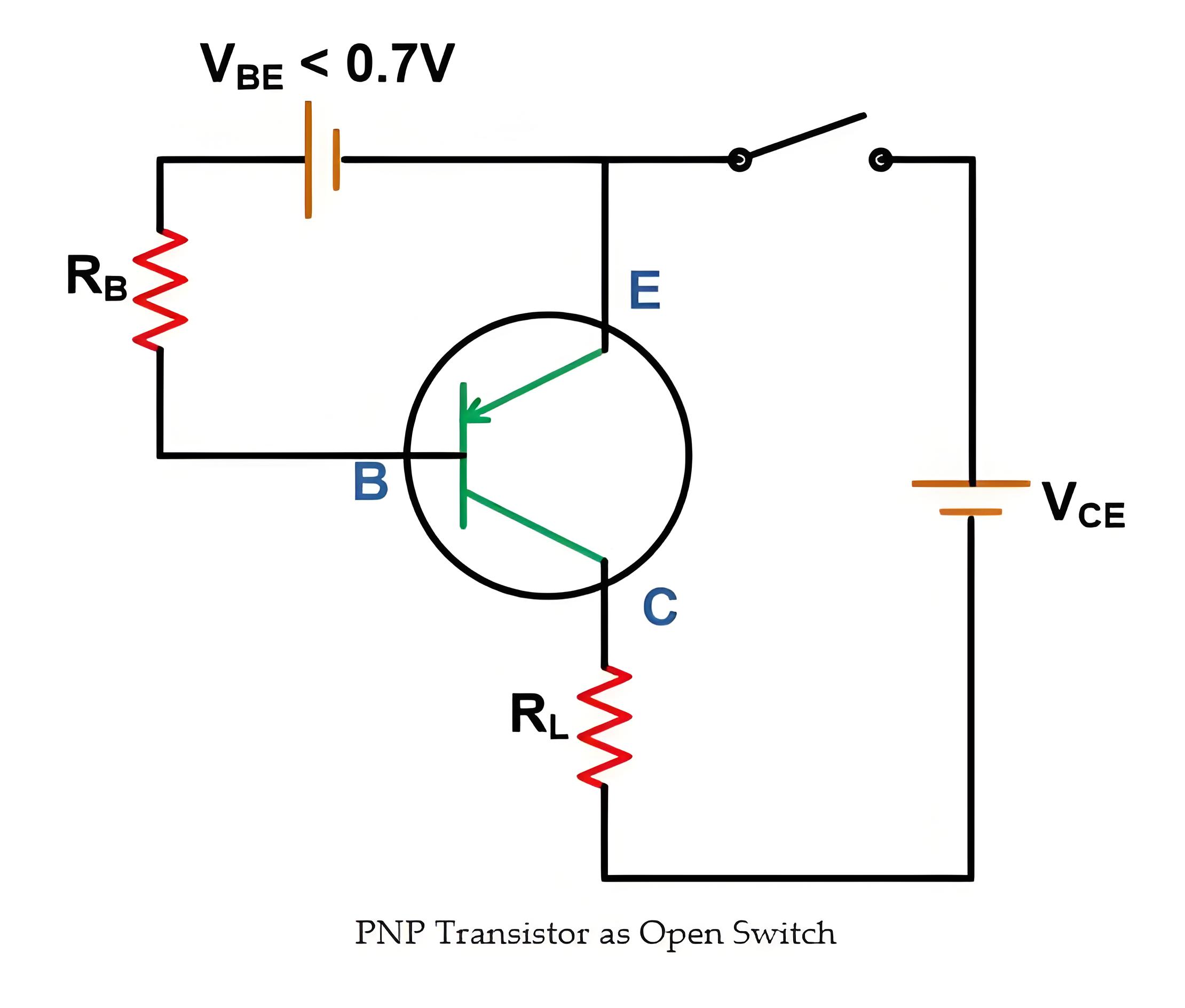
As we have seen in the working of the PNP transistor, if the Base voltage is not more negative then Emitter voltage, the current cannot flow through the device. So, Base voltage is a minimum of 0.7 V in reverse bias to conduct the transistor. It means that, if the Base voltage is zero or less than 0.7 V, the current cannot flow and it acts as an open circuit.


afe17bf94e18dc606e5d8c1ec907e7b7.jpeg


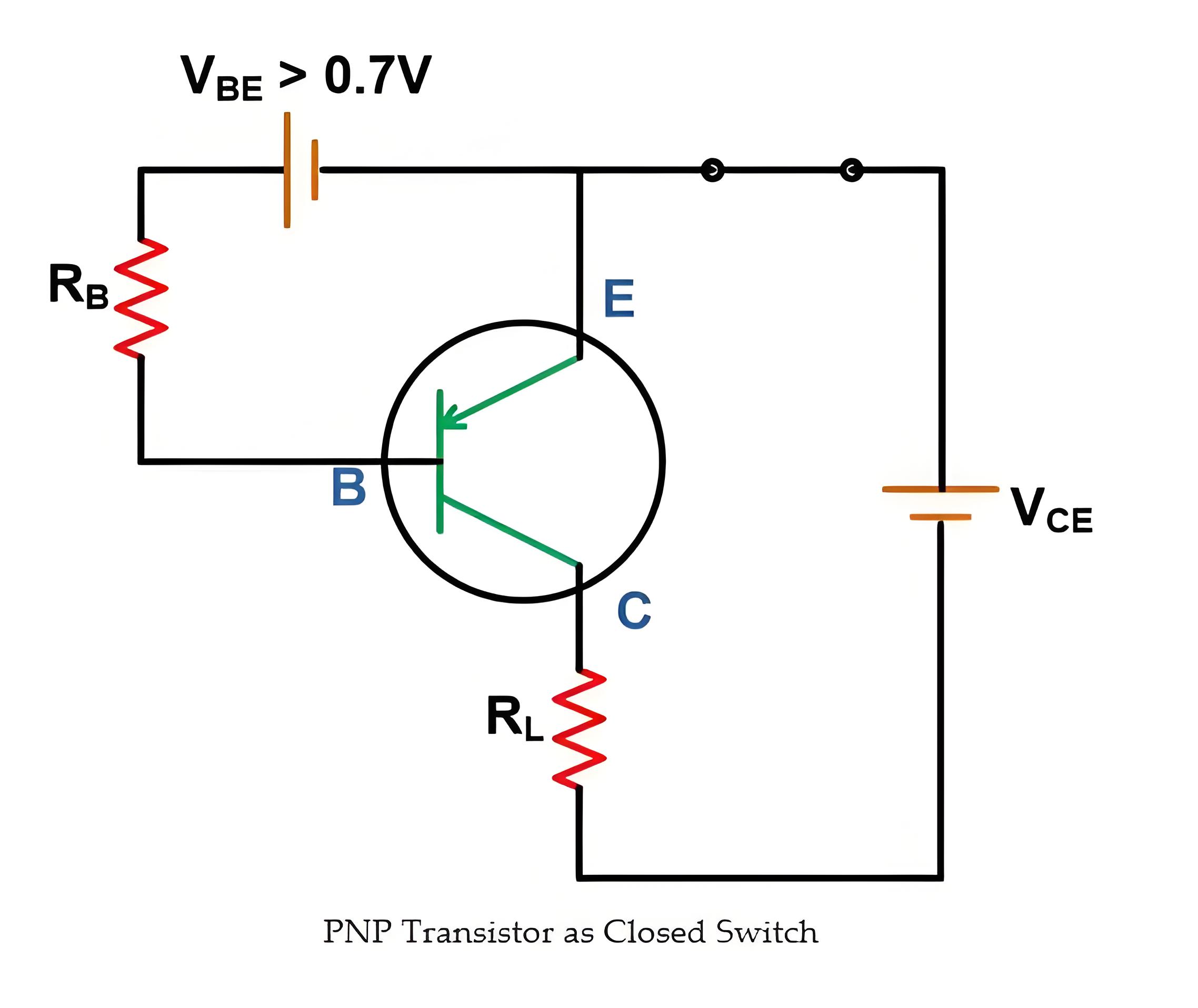
To turn ON the transistor, the Base voltage must more than 0.7 V. In this condition, the transistor acts as a close switch.


604ac0570c7b34b9254835515fd77a8e.jpeg


Encyclopedia

The Electricity Encyclopedia is dedicated to accelerating the dissemination and application of electricity knowledge and adding impetus to the development and innovation of the electricity industry.

Does a grid-connected inverter need a grid to operate?
Grid-connected inverters do need to be connected to the grid to function properly. These inverters are designed to convert direct current (DC) from renewable energy sources, such as solar photovoltaic panels or wind turbines, into alternating current (AC) that synchronizes with the grid in order to feed power into the public grid. Here are some of the key features and operating conditions of grid-connected inverters:The basic working principle of grid-connected inverterThe basic working principl
Encyclopedia
09/24/2024
Advantages of infrared generator
Infrared generator is a kind of equipment that can produce infrared radiation, which is widely used in industry, scientific research, medical treatment, security and other fields. Infrared radiation is an invisible electromagnetic wave with a wavelength between visible light and microwave, which is usually divided into three bands: near infrared, middle infrared and far infrared. Here are some of the main advantages of infrared generators:Non-contact measurement No contact: The infrared generato
Encyclopedia
09/23/2024
What is a Thermocouple?
What is a Thermocouple?Thermocouple DefinitionA thermocouple is a device that converts temperature differences into an electric voltage, based on the principle of the thermoelectric effect. It is a type of sensor that can measure temperature at a specific point or location. Thermocouples are widely used in industrial, domestic, commercial, and scientific applications due to their simplicity, durability, low cost, and wide temperature range.Thermoelectric EffectThe thermoelectric effect is the ph
Encyclopedia
09/03/2024
What is a Resistance Temperature Detector?
What is a Resistance Temperature Detector?Resistance Temperature Detector DefinitionA Resistance Temperature Detector (also known as a Resistance Thermometer or RTD) is an electronic device used to determine the temperature by measuring the resistance of an electrical wire. This wire is referred to as a temperature sensor. If we want to measure temperature with high accuracy, an RTD is the ideal solution, as it has good linear characteristics over a wide range of temperatures. Other common elect
Encyclopedia
09/03/2024
Inquiry
Download
IEE-Business is dedicated to serving the personnel in the global power industry.
Join IEE-Business, not only can you discover power equipment and power knowledge, but also canhnd like - minded friends!