Fleming’s Right-Hand Rule

Rabert T
03/09/2024

Fleming’s Right-Hand Rule is a principle in electromagnetism that describes the relationship between the direction of the current in a conductor, the direction of the magnetic field around the conductor, and the direction of the force on the conductor.

Fleming’s Right-Hand Rule states that if the thumb, index finger, and middle finger of the right hand are pointed in the direction of the current, the direction of the magnetic field, and the direction of the force on the conductor, respectively, then the fingers will curl in the direction of the force.

To use Fleming’s Right-Hand Rule, follow these steps:

Hold your right hand out with the thumb, index finger, and middle finger extended.

  • Point the thumb in the direction of the current in the conductor.

  • Point the index finger in the direction of the magnetic field around the conductor.

  • Point the middle finger in the direction in which the force on the conductor is expected to act.


1-49.jpg


What is another term for Fleming’s right-hand rule?

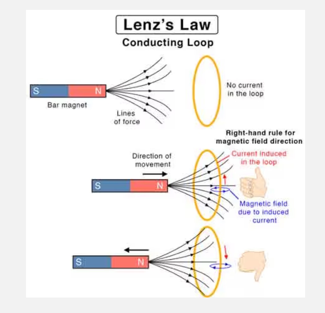
Fleming’s right hand is also known as generator rule. It specifies the direction of the induced current generated by a straight conductor flowing in a magnetic field.

Applications of Fleming’s Right-Hand Rule:

Fleming’s Right-Hand Rule is often used to predict the direction of the force on a conductor in the presence of a magnetic field.

It is particularly useful for understanding the behavior of motors and generators, which rely on the interaction between currents and magnetic fields to produce motion or electrical power.


2-19.jpg


The Right-Hand Rule is named after the British scientist John Ambrose Fleming, who first proposed it in the late 19th century.

It is one of several similar rules that are used to predict the behavior of currents and magnetic fields in various situations.

Statement: Respect the original, good articles worth sharing, if there is infringement please contact delete.

Rabert T

As an electrical engineer with 5 years of experience, I focus on transformer and circuit breaker reliability in 110/33-11kV and 33/11kV substations. I am a professional electrical engineer with experience in transformer service and maintenance.

Electrical And Electronic Symbols
An electrical symbol is a small image used to represent an electrical or electronic device or function. They are also known as circuit symbols or schematic symbols as they are used in electrical schematics and diagrams.Some basic electrical symbols include: Wires Diode Batteries Transformers Capacitors Resistors Inductors Fuses Switches Bipolar Junction Transistors Electromagnetic RelaysThere are many electrical and circuit symbols used internationally around the world. While they are mostly st
Blake
03/18/2024
Electrical Transformers – Formulas and Equations
Transformers are one of the most common types of electrical devices, and they may be found in a variety of applications within the area of electrical engineering, including power systems. Therefore, in the position of an electrical engineer, it is usually neededto compute various characteristics of a transformer in order to establish the circumstances under which it operates. In order to do this,will need to use conventional equations, which can be seen mentioned in the sections that will follow
Hobo
03/18/2024
Lenz's Law Explained
Lenz's Law, named after the Russian physicist Heinrich Lenz (1804-1865), is a fundamental principle in electromagnetism. It states that the direction of the induced electromotive force (emf) in a closed conducting loop always opposes the change in magnetic flux that caused it. This means that the induced current creates a magnetic field that opposes the initial change in magnetic flux, following the principles of conservation of energy.Understanding Lenz's Law allows us to appreciate the science
The Electricity Forum
03/18/2024
What is Shunt Resistor and How Does it Work?
In several electrical and power applications, the measurement of current flow is essential.Hence, current measurement is commonly required for monitoring and controlling applications.Depending on the kind of application, many types of current sensors with specialised current sensing technologies are available to detect (or)measure current flow.A current sensing resistor, also known as a shunt resistor, is the most prevalent methodto measure current flow in any application.This postdescribes shun
Rabert T
03/12/2024
Inquiry
Download
IEE-Business is dedicated to serving the personnel in the global power industry.
Join IEE-Business, not only can you discover power equipment and power knowledge, but also canhnd like - minded friends!