1. Introduction
Energy is essential for societal operation and development. To meet national energy - conservation and emission - reduction policies, improving resource utilization—critical for power enterprises—is necessary. Multi - stage rural grid upgrades drive distribution transformer development. Despite high efficiency, widespread transformers still face significant overall losses due to capacity and usage issues; 70% of medium - and low - voltage grid losses come from distribution transformers. Rural grids have concentrated, season - affected loads, with large peak - valley differences lowering transformers’ average load rates. Using capacity - regulating transformers in such areas helps match capacity to load, ensuring economic and safe operation, reducing overloads and energy waste. Designing an auto - capacity - regulating special transformer offers technical breakthroughs and practical/theoretical value.
2. Transformer Loss Generation Mechanism
Transformers, key in distribution networks for energy distribution and voltage/current adjustment, suffer large power losses during normal operation—comprising short - circuit (load) and no - load losses.
Short - circuit loss (load loss) occurs when rated current flows through windings under load. Detected via short - circuit tests (applying low voltage to the primary, measuring rated current on the secondary, ignoring core loss), it approximates copper loss. This loss scales with load, restricted by load coefficients and rated short - circuit loss.
3. Design & Implementation of Auto - Capacity - Regulating Special Transformer
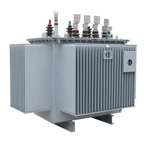
3.1 Capacity - Regulating Transformer Structure
The adopted D - Y tap - changing distribution transformer uses different winding modes for large - and small - capacity operations: delta (D) for large capacity, star (Y) for small capacity (called star - delta conversion). Its low - voltage windings combine 27% - turn and 73% - turn wires, with the latter’s cross - section ~1/2 of the former.
3.2 Auto - Capacity - Regulation Realization
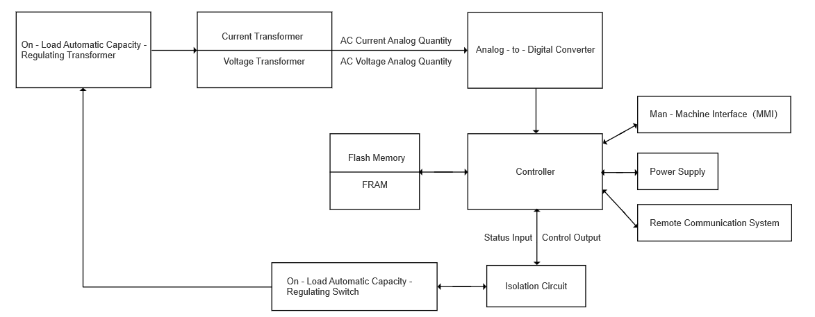
On - load auto - capacity - regulating transformers rely on automatic control modules: data acquisition, storage, transformers, human - machine interaction, power supply, and I/O loops. Voltage/current transformers collect signals; analog circuits with microprocessors process them. Processed data stores in memory for external interfaces or future exchanges. Figure 1 shows the auto - control system composition.
3.3 Control Process of the Automatic Control System
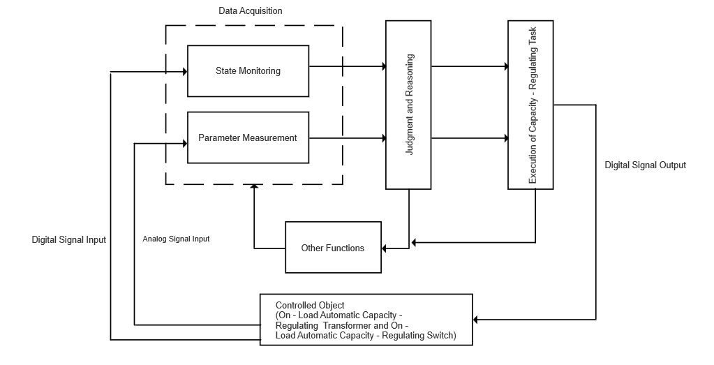
The analog current of the capacity-regulating transformer and the secondary side voltage are collected by the on-load capacity-regulating controller. Combined with the switch state quantity of the capacity-regulating switch, numerical judgment can be implemented according to the operating condition characteristics and operating parameters of the controlled object. Then, it is determined whether the conditions for executing the task are met based on the actual control conditions.
If the conditions are met and the capacity of the distribution transformer needs to be adjusted, the program will switch to the task module for transformer capacity adjustment. After completing the capacity adjustment task, it will enter other auxiliary function modules. If the conditions for task operation are not met, or there is no immediate need to adjust the transformer capacity, the program will directly enter other auxiliary function modules. Figure 2 shows the flow chart of the automatic control system.
3.4 Hardware Structure of the On-Load Capacity-Regulating Automatic Control System
The hardware structure of the on-load capacity-regulating automatic control system mainly consists of a signal acquisition unit, a data communication unit, an input unit, an output unit, a control panel system, a power crystal oscillator, and a clock circuit.
The on-load automatic capacity-regulating system has high anti-interference ability and hardware reliability mainly because industrial-grade chips are selected for all its components. Moreover, the electromagnetic compatibility of components and circuits is considered during circuit design. This ensures that the on-load automatic capacity-regulating system has a high level of operational reliability and electrical safety, and can meet usage requirements even in harsh electrical environments.
4. Conclusion
In distribution networks, the widespread use of a large number of distribution transformers means that the current losses in these transformers account for a relatively high proportion of the total losses in the distribution network. Rural electricity loads are constrained by unfavorable conditions such as seasonal changes, short annual utilization periods, and frequent occurrences of no - load or light - load states. As a result, the situation where the load rate of transformers stays within a reasonable operating range is relatively rare.
Capacity - regulating transformers can adjust according to load fluctuations and the state of the capacity - regulating switch. By changing the connection mode of transformer windings, they give transformers the characteristic of adjustable capacity. Therefore, reasonably installing capacity - regulating transformers in rural power grid areas with large loads and frequent voltage fluctuations has a relatively obvious effect on circuit energy conservation and loss control.
With the continuous development and progress of electricity - using technologies, the functional improvements of on - load automatic capacity - regulating transformers are also becoming increasingly perfect. It is believed that automatic capacity - regulating special transformers will achieve new breakthroughs in the direction of energy conservation and loss reduction in future distribution networks.