• Product
  • Suppliers
  • Manufacturers
  • Solutions
  • Free tools
  • Knowledges
  • Experts
  • Communities
Search


What is Miniature Circuit Breaker?

Encyclopedia
Field: Encyclopedia
0
China


What is Miniature Circuit Breaker?


MCB Definition


An MCB is defined as an automatically operated switch that protects low voltage electrical circuits from excess current due to overload or short circuit.


Fuse vs MCB


Nowadays miniature circuit breakers (MCBs) are much more commonly used in low voltage electrical networks instead of fuses. The MCB has many advantages compared to a fuse:


  • It automatically switches off the electrical circuit during the abnormal conditions of the network (both overload and fault conditions). The MCB is much more reliable in the detection of such conditions, is it is more sensitive to change in current.


  • As the switch operating knob comes at its off position during tripping, the faulty zone of the electrical circuit can easily be identified. But in case of a fuse, the fuse wire should be checked by opening fuse grip or cutout from fuse base, for confirming the blow of fuse wire. Thus is it much detect if an MCB has been operated compared to a fuse.


  • Quick restoration of supply can not be possible in case of fuse, as fuses have to be rewirable or replaced for restoring the supply. But in the case of an MCB, quick restoration is possible by (literally) flipping a switch.


  • The handling of an MCB is more electrically safe than a fuse.


  • MCBs can be controlled remotely, whereas fuses can not.


Because of these many advantages of MCB over fuse units, in modern low voltage electrical network, the miniature circuit breaker is almost always used instead of a fuse.The only one disadvantage of MCB over fuse is that this system is costlier than a fuse unit system.


Working Principle Miniature Circuit Breaker


There are two ways an MCB operates: through the thermal effect of overcurrent and the electromagnetic effect of overcurrent. In thermal operation, a bimetallic strip heats and bends when continuous overcurrent flows through the MCB.


This deflection of the bimetallic strip releases a mechanical latch. As this mechanical latch is attached to the operating mechanism, it causes to open the miniature circuit breaker contacts.


During short circuits, the sudden rise in current causes the plunger in the tripping coil to move. This movement strikes the trip lever, immediately releasing the latch mechanism and opening the circuit breaker contacts. This explains the MCB’s working principle.


Miniature Circuit Breaker Construction


Miniature circuit breaker construction is very simple, robust and maintenance-free. Generally, an MCB is not repaired or maintained, it just replaced by a new one when required. A miniature circuit breaker has normally three main constructional parts. These are:


Frame of Miniature Circuit Breaker


The frame of a miniature circuit breaker is a molded case. This is a rigid, strong, insulated housing in which the other components are mounted.


Operating Mechanism of Miniature Circuit Breaker


The operating mechanism of a miniature circuit breaker provides the means of manual opening and closing operation of a miniature circuit breaker. It has three-positions “ON,” “OFF,” and “TRIPPED”. The external switching latch can be in the “TRIPPED” position if the MCB is tripped due to over-current.


When manually switch off the MCB, the switching latch will be in the “OFF” position. In the closed condition of an MCB, the switch is positioned at “ON”. By observing the positions of the switching latch one can determine the condition of MCB whether it is closed, tripped or manually switched off.


Trip Unit of Miniature Circuit Breaker


The trip unit is the main part, responsible for the proper working of the miniature circuit breaker. Two main types of trip mechanisms are provided in MCB. A bimetal provides protection against overload current and an electromagnet provides protection against short-circuit current.


Operation of Miniature Circuit Breaker


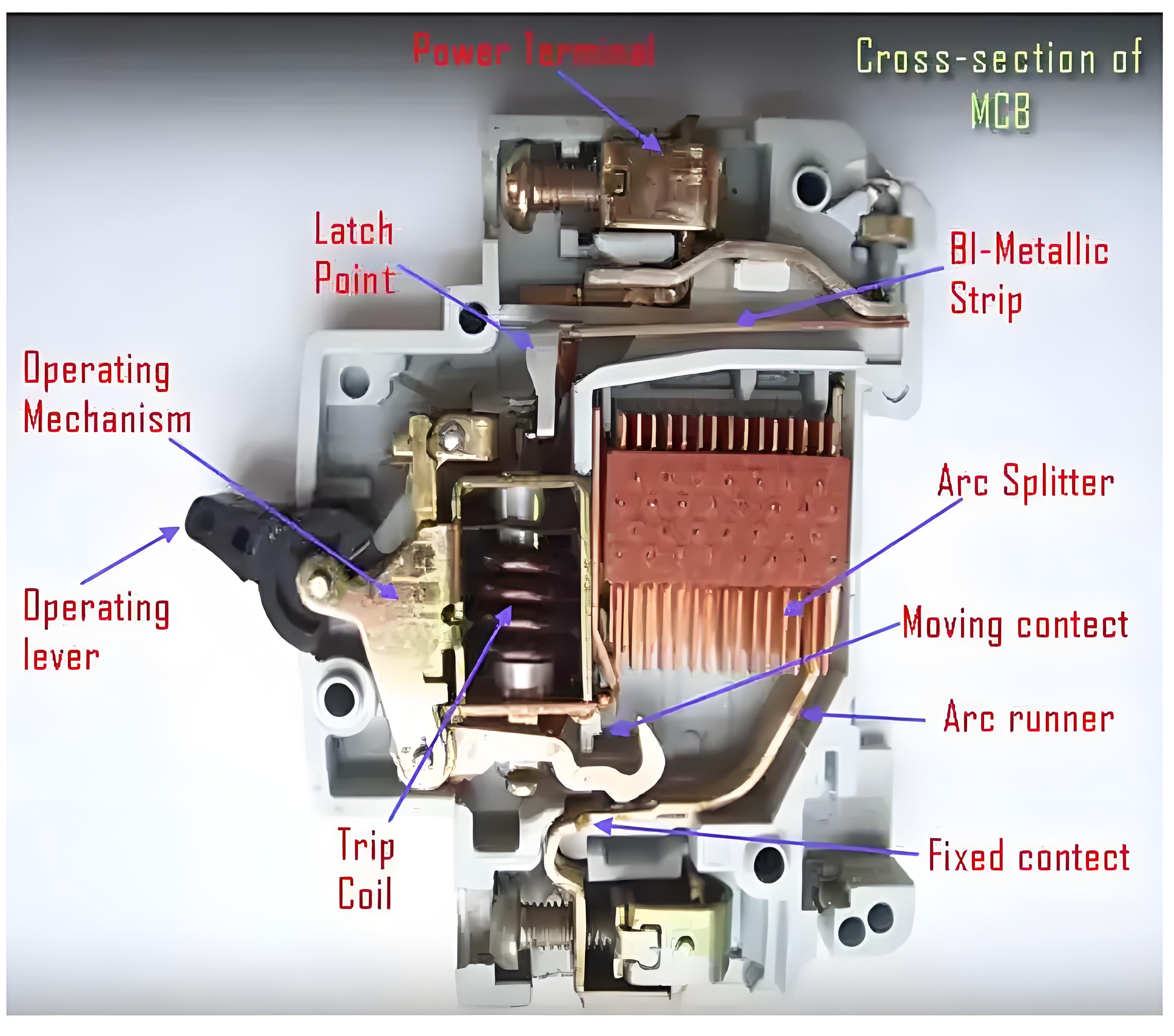
There are three mechanisms provided in a single miniature circuit breaker to make it switched off. If we carefully observe the picture beside, we will find there is mainly one bimetallic strip, one trip coil and one-hand operated on-off lever.


The electric current-carrying path of a miniature circuit breaker shown in the picture is as follows. First left-hand side power terminal – then bimetallic strip – then-current coil or trip coil – then moving contact – then fixed contact and – lastly right had side power terminal. All are arranged in series.


c9234a9a8708869bdb84718d3c7f964b.jpeg


If the circuit is overloaded for a long time, the bimetallic strip becomes overheated and deformed. This deformation of bimetallic strip causes, displacement of latch point. The moving contact of the MCB is so arranged by means of spring pressure, with this latch point, that a little displacement of latch causes, release of spring and makes the moving contact to move for opening the MCB.


The current coil or trip coil is placed in such a manner, that during short circuit fault the MMF of that coil causes its plunger to hit the same latch point and make the latch to be displaced. Hence the MCB will open in the same manner.


Again when the operating lever of the miniature circuit breaker is operated by hand, that means when we make the MCB at off position manually, the same latch point is displaced as a result moving contact separated from fixed contact in the same manner.


Regardless of the operating mechanism – e.g. due to the deformation of the bimetallic strip, or due to the increased MMF of the trip coil, or due to manual operation – the same latch point is displaced and same deformed spring is released. This is ultimately responsible for the movement of the moving contact. When the moving contact separated from fixed contact, there may be a high chance of arc.


This arc then goes up through the arc runner and enters into arc splitters and is finally quenched. When we switch on an MCB, we actually reset the displaced operating latch to its previous on position and make the MCB ready for another switch off or trip operation.


Give a tip and encourage the author!
Recommended
What are the principles of forced re-energization of transmission lines?
Principles of Forced Re-energization of Transmission LinesRegulations for Forced Re-energization of Transmission Lines Correctly select the forced re-energization end of the line. If necessary, change the connection configuration before forced re-energization, taking into account the reduction of short-circuit capacity and its impact on grid stability. There must be a transformer with its neutral point directly grounded on the busbar at the forced re-energization end. Pay attention to the impact
Edwiin
09/04/2025
Analysis of Accident Handling in Transmission Lines
Analysis of Transmission Line Fault HandlingAs a fundamental component of the power grid, transmission lines are widely distributed and numerous, often exposed to diverse geographical and climatic conditions, making them highly susceptible to faults. Common causes include overvoltage, pollution flashover, insulation damage, tree encroachment, and external damage. Line tripping is one of the most frequent faults in power plant and substation operations, with fault types including single-phase-to-
Leon
09/04/2025
The difference between transmission and distribution lines
Transmission lines and distribution lines are both used to carry electrical power from one location to another. However, they differ significantly in key aspects such as primary function, voltage levels, phase configuration, and conductor placement. These differences are essential for understanding their distinct roles in the power system.The Difference Between Transmission and Distribution Line is given below in the tabulated form.Electricity generation is a critical component of the power syst
Edwiin
09/04/2025
Ensuring Reliability: A Deep Dive into Transformer Maintenance
IntroductionElectric transformers are the backbone of modern power distribution systems, silently enabling the reliable delivery of electricity to homes, businesses, and industries. As these critical assets age and the demand for uninterrupted power grows, the importance of diligent transformer maintenance has never been greater. This essay explores the essential role of transformer maintenance, highlighting the value of proactive care, the impact of advanced diagnostic technologies, and the tra
Vziman
09/03/2025
Related Products
  • 550m width manual Cradle
  • Indoor Vacuum Load Break Switch
  • 1-Core Straight throught joint kit
  • 24kV Solid Insulation Ring Main Unit/RMU
Seed Inquiry
Download
Get the IEE Business Application
Use the IEE-Business app to find equipment, obtain solutions, connect with experts, and participate in industry collaboration anytime, anywhere—fully supporting the development of your power projects and business.