• Product
  • Suppliers
  • Manufacturers
  • Solutions
  • Free tools
  • Knowledges
  • Experts
  • Communities
Search


How to Use a Digital Multimeter?

Encyclopedia
Encyclopedia
Field: Encyclopedia
0
China


How to Use a Digital Multimeter?


Digital Multimeter Definition


A digital multimeter is defined as a device that measures electrical parameters like voltage, current, and resistance, displaying the results digitally.


9d59f66be255c59be136437d3f0ecf70.jpeg


Main Parts


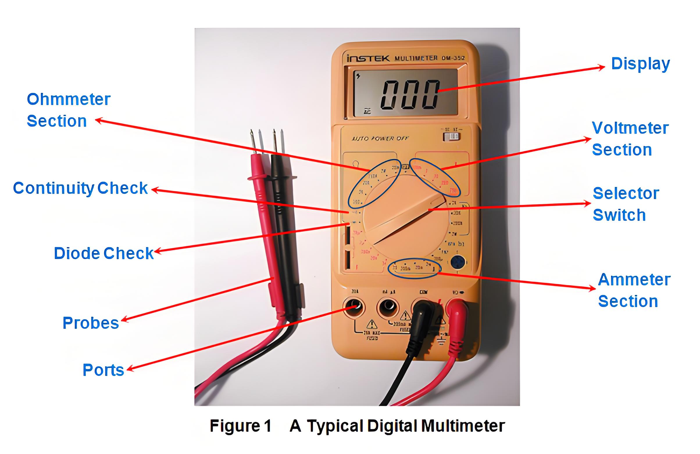
The main parts of a digital multimeter include the display, selection switch, ports, and probes, each crucial for accurate measurements.


Measuring Current


To measure current with a digital multimeter, it mimics an ammeter. Insert the red probe into the mA socket for low current or the 20A socket for high current. Connect the meter in series with the circuit. Set the switch to the expected current range. When the power is on, the meter will display the current flowing through the circuit.


Measuring Voltage


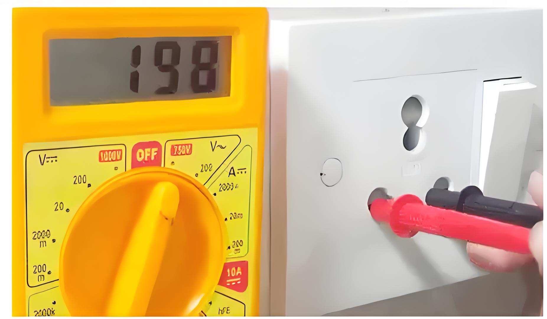
To measure voltage with a digital multimeter, it acts like a voltmeter. Insert the red probe into the ‘V’ socket and the black probe into the ‘COM’ socket. Select the expected voltage range and choose either AC or DC. Connect the leads in parallel with the component or point where the voltage is measured. The meter will display the voltage value.


3e6886681db14babdb1f21365ed97264.jpeg


Measuring Resistance


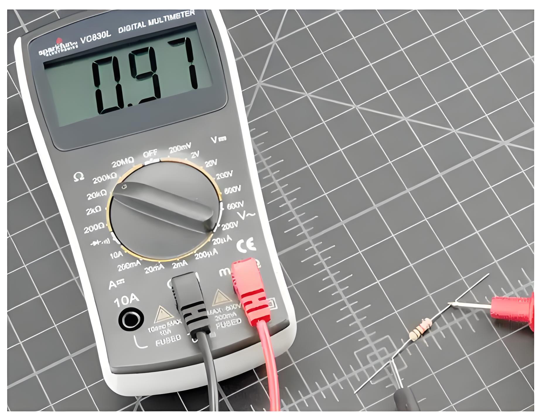
In this case, we configure the multimeter to act like an ohmmeter. Here the red and the black probes of the multimeter are inserted into the sockets marked as ‘V’ and ‘COM’, respectively while the selection switch is set to an expected range in ohmmeter region (Figure 1). Now, the leads need to be connected across the component whose resistance is to be known. On doing so, we get a reading in the display part of the multimeter which reads the value of the resistance.


61d153e133793a03d9a55ca473790f7d.jpeg


Diode Check


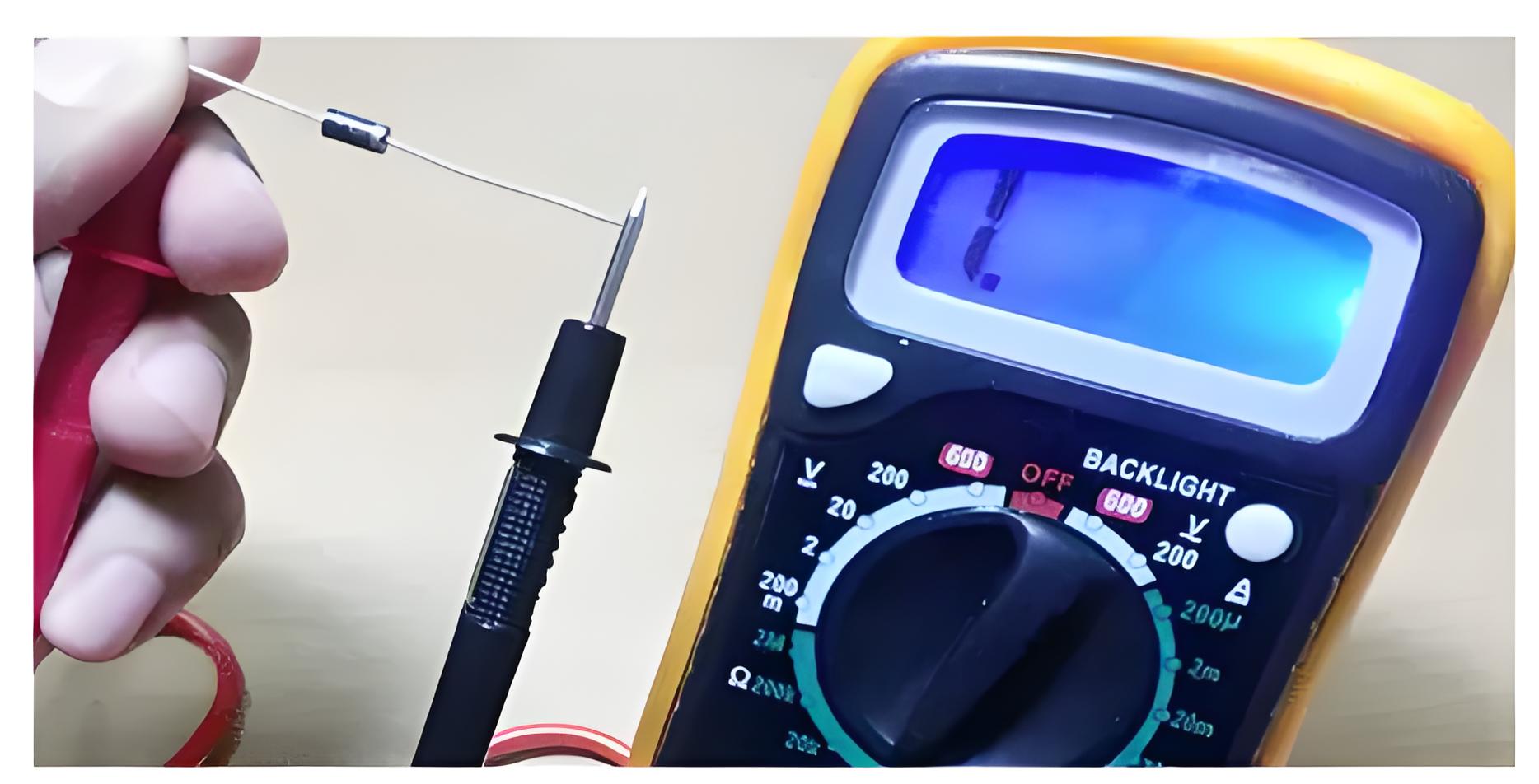
For this case, insert the probes into the sockets as that in the case of voltage measurement and set the selection switch to point towards diode check position shown in Figure 1. Now when the red lead of the multimeter is connected to positive terminal of the diode while its negative lead is connected to the negative terminal of the diode, then we have to get a low reading on the multimeter. 


On the other hand, if we connect the red lead to the negative terminal of the diode and the black to the positive terminal, then we have to get a high value. If the readings obtained are as per our expectation, then we say that the diode is working properly; else no.


279b8fd5205eacad1931ece3e7c662d3.jpeg


Checking Continuity


Continuity check is used to know whether there exists any low resistance path via two points i.e. to check whether the points are short or not. To accomplish this task, the probes are inserted into the sockets as that in the case of voltage measurement and selector switch is made to point towards continuity check position (Figure 1). Then, the points to be tested are touched with the leads of the probes. Now, if the multimeter beeps out, then it means that the points are shorted or else the resistance between them can be read out from the display.

Give a tip and encourage the author!
Recommended
What Are Combined Transformer Standards? Key Specs & Tests
Combined Instrument Transformers: Technical Requirements and Testing Standards Explained with DataA combined instrument transformer integrates a voltage transformer (VT) and a current transformer (CT) into a single unit. Its design and performance are governed by comprehensive standards covering technical specifications, testing procedures, and operational reliability.1. Technical RequirementsRated Voltage:The primary rated voltages include 3kV, 6kV, 10kV, and 35kV, among others. The secondary v
Edwiin
10/23/2025
MVDC: Future of Efficient, Sustainable Power Grids
The Global Energy Landscape Is Undergoing a Fundamental Transformation toward a "fully electrified society," characterized by widespread carbon-neutral energy and the electrification of industry, transportation, and residential loads.In today’s context of high copper prices, critical mineral conflicts, and congested AC power grids, Medium-Voltage Direct Current (MVDC) systems can overcome many limitations of traditional AC networks. MVDC significantly enhances transmission capacity and efficienc
Edwiin
10/21/2025
Grounding Causes of Cable Lines and the Principles of Incident Handling
Our 220 kV substation is located far from the urban center in a remote area, surrounded primarily by industrial zones such as Lanshan, Hebin, and Tasha Industrial Parks. Major high-load consumers in these zones—including silicon carbide, ferroalloy, and calcium carbide plants—account for approximately 83.87% of our bureau’s total load. The substation operates at voltage levels of 220 kV, 110 kV, and 35 kV.The 35 kV low-voltage side mainly supplies feeders to ferroalloy and silicon carbide plants
Felix Spark
10/21/2025
Overhead Power Lines & Towers: Types, Design & Safety
Besides ultra-high voltage AC substations, what we encounter more frequently are power transmission and distribution lines. Tall towers carry conductors that leap across mountains and seas, stretching into the distance before reaching cities and villages. This is also an interesting topic—today, let's explore transmission lines and their supporting towers.Power Transmission and DistributionFirst, let’s understand how electricity is delivered. The electric power industry primarily consists of fou
Encyclopedia
10/21/2025
Send inquiry
Download
Get the IEE Business Application
Use the IEE-Business app to find equipment, obtain solutions, connect with experts, and participate in industry collaboration anytime, anywhere—fully supporting the development of your power projects and business.