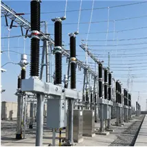
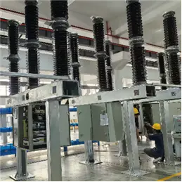
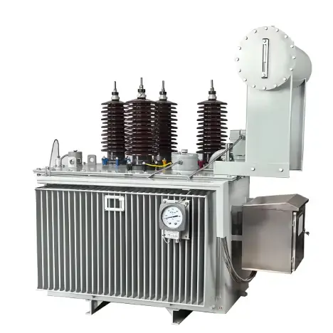
The CT20 spring operating mechanism uses a spring-charged system and is designed for RHB-series porcelain-post SF6 circuit breakers (11 kV–550 kV). Three interrupter chambers share a single mechanism with three-pole gang operation. Its core energy logic is: the closing spring drives closing → the closing stroke simultaneously charges the opening spring → the opening spring independently drives opening. The mechanism offers high reliability, low noise, and minimal maintenance, with a maintenance interval of up to 30 years.
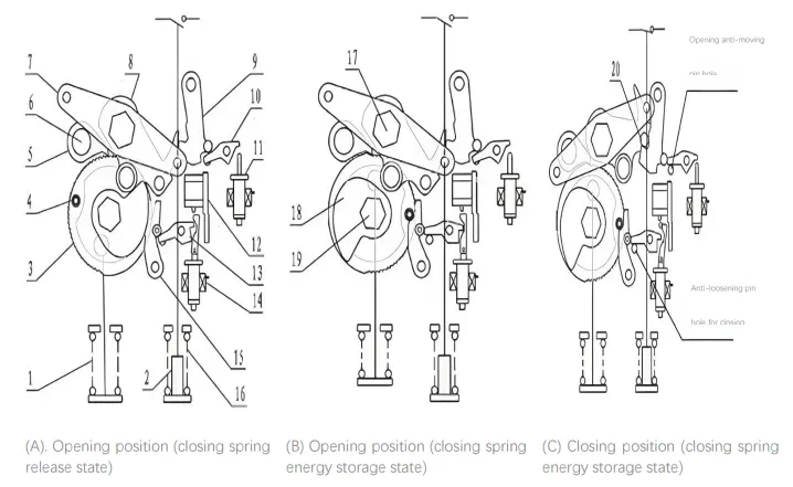
2. Key Components
| Component |
Function |
| Closing spring (1) |
Drives the closing operation |
| Opening spring (16) |
Drives the opening operation |
| Ratchet wheel (3) + Pawl (5) |
Transmits and locks charging energy |
| Charging latch (15) + Latch pin (4) |
Locks the closing spring in the charged state |
| Closing trigger (13) + Closing solenoid (14) |
Receives the closing command and releases the charging latch |
| Cam (18) + Output lever (7) |
Transfers spring energy to the circuit breaker |
| Closing latch (9) + Closing latch pin (20) |
Locks the breaker in the closed position |
| Opening trigger (10) + Opening solenoid (11) |
Receives the opening command and releases the closing latch |
| Mechanical anti-pump device (12) |
Prevents repeated closing |
3. Closing Spring Charging Process
After the circuit breaker closes, the limit switch activates and the charging motor starts. The motor drives the charging lever to oscillate via bevel gears. The pawls alternately advance the ratchet wheel, compressing the closing spring through the spring lever and pull rod. Once the pin passes the dead centre, the closing spring back-drives the charging lever by about 5°, allowing the latch pin (4) to engage the charging latch (15). The motor then de-energizes, completing the charging cycle.
4. Closing Operation
- Closing command received → The closing solenoid (14) operates, and its plunger strikes the closing trigger (13).
- Charging latch released → The trigger rotates and releases the charging latch (15).
- Spring releases to drive closing → The closing spring drives the ratchet wheel counter-clockwise. The coaxial cam (18) strikes the closing roller on the output lever (7), moving the lever upward.
- Closed position locked → The closing latch pin (20) is held by the closing latch (9).
- Opening spring charged simultaneously → The opening spring lever, coaxial with the output lever, compresses the opening spring (16).
- Automatic recharging → The limit switch activates, and the motor recharges the closing spring.
5. Opening Operation
- Opening command received → The opening solenoid (11) operates, and its plunger strikes the opening trigger (10).
- Closing latch released → The trigger rotates and releases the closing latch (9).
- Opening spring releases → It drives the output lever to rotate, converting motion through links, the drive shaft, and horizontal pull rods to move the moving contact and complete opening.
- Buffering and limiting → The opening buffer absorbs residual energy and limits the final position of the moving contact.
6. Anti-Pump / Anti-Pumping Device
When the breaker closes onto a fault while the closing command remains present, the anti-pump device ensures only one close–open (CO) sequence occurs, preventing repeated closing. The CT20 features mechanical anti-pumping (12) plus electrical anti-pumping for dual protection.
Mechanical anti-pumping principle (industry-typical): When the closing solenoid is energized, its core rod depresses the anti-pumping pin and then strikes the trigger. After closing, the trip rod is held by the anti-pumping pin in an inclined position, preventing it from resetting and striking the trigger again.
7. Compliance with IEC Standards
Applicable Standards
- IEC 62271-1:2017 – Common specifications for high-voltage switchgear and controlgear
- IEC 62271-100:2021 – High-voltage alternating-current circuit breakers, including operating mechanism requirements
- Chinese equivalent: GB/T 1984-2024
Key Clause Comparison
| IEC Clause |
Requirement |
CT20 Capability |
| Rated operating sequence |
O – t – CO – t′ – CO |
O–0.3 s–CO–3 min–CO (auto-reclosing type) |
| Mechanical endurance |
M1 = 2,000 operations / M2 = 10,000 operations |
Class M2 (≥10,000 operating cycles) |
| Anti-pumping |
Only one CO operation while the closing command persists |
Mechanical + electrical anti-pumping |
| Operating voltage |
Closing 85%–110%, opening 65%–120% |
AC/DC motor; rated 220 V / 110 V / 48 V / 24 V |
Typical Timing Parameters
| Parameter |
Typical CT20 Value |
| Closing time |
≤100 ms |
| Opening time |
≤60 ms |
| Charging time |
≤15 s |
| Three-phase closing/opening simultaneity |
≤5 ms / ≤3 ms |
8. Operating Sequence Overview
Motor starts → Closing spring charges → Charging latch (15) locks
Closing command → Closing solenoid (14) → Releases latch (15)
↓
Closing spring releases → Breaker closes → Closing latch (9) locks
↓
Opening spring (16) charges simultaneously Motor recharges automatically
↓
Opening command → Opening solenoid (11) → Releases latch (9)
↓
Opening spring releases → Breaker opens → Mechanism returns to standby

 Login