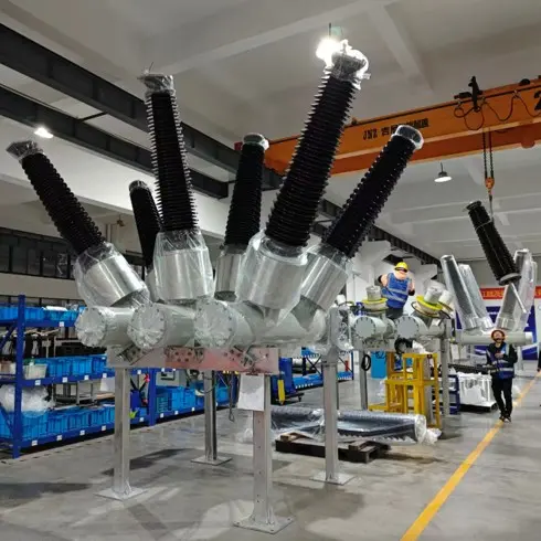
Application Scope: Outdoor live‑tank SF6 circuit‑breakers adopting self‑blast arc‑extinguishing principle (thermal‑expansion plus auxiliary compression), equipped with spring operating mechanisms. This document matches the construction of this type of arc‑extinguishing chamber and complies with the technical definition for self‑energy arc‑extinguishing principle for high‑voltage AC circuit‑breakers.
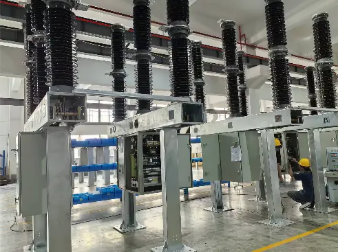
SF6 live-tank circuit breakers in workshop
What Is the Basic Arc‑Extinguishing Mechanism of the Arc‑Extinguishing Chamber?
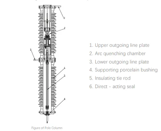
For this type of circuit‑breaker, SF6 gas serves as both insulating and arc‑quenching medium. The arc‑extinguishing chamber applies the self‑blast (self‑energy thermal‑expansion + auxiliary compression) arc‑extinguishing principle. Encapsulated inside the support porcelain bushing, it is the core interrupting unit of the circuit‑breaker.
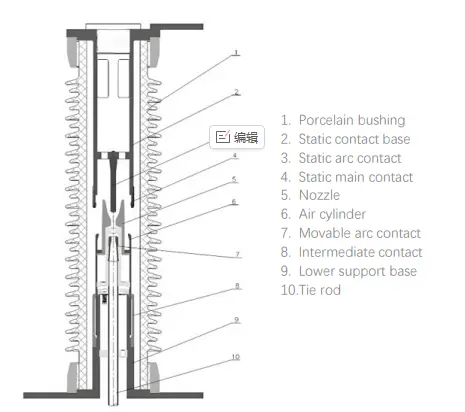
Its main components include porcelain bushing, fixed‑contact base, fixed main contact, fixed arcing contact, nozzle, cylinder, moving arcing contact, intermediate contact, lower support base and insulating tie rod.
There are two functional chambers inside the arc‑extinguishing chamber, which are prerequisites for understanding valve operation:
- Thermal‑expansion chamber: Adjacent to the arc zone. It receives high‑temperature SF6 gas flow heated by electric arcs and builds blast pressure by utilizing arc energy.
- Gas‑compression chamber: During opening operation, the relative motion between the cylinder and the piston compresses internal SF6 gas, providing gas source for auxiliary compression blast.
The two chambers are connected via valve passages. Upon opening command, the opening spring drives rigid moving assemblies including cylinder, moving arcing contact and tie rod to move downwards.
Firstly the fixed main contact separates from the moving main contact, and operating current transfers to the still‑closed arcing contacts. Afterwards the arcing contacts part and generate electric arc. A directional SF6 gas flow generated by the pressure difference between the two chambers blasts and extinguishes the arc at AC current zero.
Check valve and elastic pressure‑relief valve control gas flow direction between chambers as well as upper pressure limit of gas‑compression chamber. They realize reliable interruption across full‑current range and reduce the operating‑energy demand of the spring operating mechanism.
Standard Note: According to IEC 62271‑100, circuit‑breakers shall pass full‑range interrupting tests, covering rated short‑circuit interrupting current as well as small inductive and small capacitive switching conditions. The two valves are critical components to eliminate the interruption dead‑zone.
How Does the Check Valve (Non‑Return Valve) Operate?
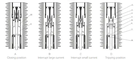
Installation Location: Mounted on the lower passage of thermal‑expansion chamber inside cylinder. It acts as on‑off control element between thermal‑expansion chamber and gas‑compression chamber. It only permits one‑way gas flow and opens and closes automatically, driven by the differential pressure across its two sides, with no external actuation required.
Core Function: Automatically switch blast gas source according to interrupting current magnitude, realize thermal‑expansion self‑blast for high‑current interruption and auxiliary compression blast for low‑current interruption, and guarantee effective blast pressure over full‑current range.
High Short‑Circuit Current Interruption: Check Valve Closes
During short‑circuit fault interruption, arc energy is huge. High‑temperature SF6 gas flow from arc zone flows into thermal‑expansion chamber and becomes low‑temperature high‑pressure SF6 after heat exchange. When pressure of thermal‑expansion chamber is higher than that of gas‑compression chamber, differential pressure presses check valve tightly closed. It blocks gas back‑flow to gas‑compression chamber and seals high‑pressure gas generated by arc energy inside thermal‑expansion chamber.
At AC current zero, high‑pressure SF6 stored in thermal‑expansion chamber blasts towards contact gap at high speed. It cools and sweeps plasma, rapidly restores dielectric strength across open contact gap and completes arc extinction. This is the thermal‑expansion self‑blast interruption mode.
Low‑Current Interruption (several kA and below, small inductive / capacitive current): Check Valve Opens
Under low‑current condition, arc energy is limited and pressure rise inside thermal‑expansion chamber is insufficient. Continuous compression during opening movement makes pressure inside gas‑compression chamber higher than thermal‑expansion chamber. The differential pressure pushes check valve open. Compressed SF6 inside gas‑compression chamber flows towards contact gap through check valve.
At current zero, this pressurized SF6 airflow quenches the arc, known as auxiliary compression blast interruption mode.
Brief Summary: The check valve works as a differential‑pressure‑driven gas‑source selector between two chambers. It locks to retain self‑blast pressure of thermal‑expansion chamber under heavy short‑circuit current; it opens to adopt compressed gas from gas‑compression chamber under low‑current condition. It eliminates low‑current interrupting dead zone of self‑energy arc‑extinguishing design, and ensures stable interrupting capability ranging from rated short‑circuit current down to small switching currents.
Compliance Note: Type‑test specified in IEC 62271‑100 includes interruption verification at multiple current amplitudes. The opening‑closing pressure characteristic of this valve shall cover all test‑current levels to avoid insufficient blast pressure and interruption failure during low‑current switching.
What Performance Does the Elastic Pressure‑Relief Valve (Pressure‑Reducing Valve + Pressure‑Reducing Spring Assembly) Deliver?
Installation Location: Installed at bottom of gas‑compression chamber inside cylinder, working cooperatively with gas‑return valve at chamber base.
Important Reminder: This valve is NOT the over‑pressure relief device for arc‑extinguishing chamber. It is an operational pressure‑regulating valve that activates during every normal opening operation. It only clamps pressure inside gas‑compression chamber and will NOT release pressure for thermal‑expansion chamber.
Core Function: Limit maximum reaction force of gas‑compression chamber, substantially reduce required operating energy of spring operating mechanism, decrease mechanical load on mechanism components and improve mechanical service life.
Working Process: During opening travel, downward movement of cylinder continuously compresses SF6 inside gas‑compression chamber and internal pressure rises gradually. When pressure reaches pre‑set threshold value, gas force overcomes spring pre‑load and lifts open elastic pressure‑relief valve.
Then gas‑compression chamber operates in a mixed condition: gas keeps being compressed while excess gas is discharged outwards. Chamber pressure is clamped near calibrated value instead of rising without limit.
The operating mechanism no longer needs to counteract steeply‑rising gas reaction force, which greatly reduces demand for opening operating energy and mitigates mechanical stress on springs, connecting rods, rotating shafts and other parts.
Brief Summary: The elastic pressure‑relief valve acts as pressure‑clamping and reaction‑force limiter for gas‑compression chamber. Moderate sacrifice of upper‑limit pressure for compression chamber brings prominent reduction of mechanism operating energy. It matches output capacity of spring‑driven mechanism and realizes product features of low operating‑power requirement and high reliability.
Key Distinction (Easily‑confused items)
- This elastic pressure‑relief valve: a working valve for the arc‑extinguishing cycle. It activates during every opening operation once the calibrated pressure is reached; this is part of normal circuit‑breaker operation.
- Equipment over‑pressure relief device: fault‑protection component. It only triggers under abnormal overpressure inside arc‑extinguishing chamber and never participates in normal opening‑closing cycles.
How Do the Two Valves Co‑Operate?
| Component |
Installation Location |
Status during high short‑circuit‑current interruption |
Status during low‑current interruption |
Core Function |
| Check Valve |
Passage connecting thermal‑expansion chamber and gas‑compression chamber (lower cylinder section) |
Closed; high‑pressure gas retained in thermal‑expansion chamber for self‑blast interruption |
Open; compressed gas supplied from gas‑compression chamber for auxiliary blast |
Switch blast gas source by differential pressure, achieve reliable interruption for full‑range currents |
| Elastic Pressure‑Relief Valve |
Bottom of gas‑compression chamber |
Opens at set pressure; vent excess gas of compression chamber to reduce mechanism reaction force |
Opens at set pressure; vent excess gas of compression chamber to reduce mechanism reaction force |
Clamp maximum pressure of gas‑compression chamber, reduce opening operating energy and protect operating mechanism |
How to Understand the Overall Design Logic of the Two Valves?
The check valve governs arc‑quenching blast performance. For high‑current and low‑current scenarios, it selects blast gas source between arc‑generated self‑energy (thermal‑expansion chamber) and mechanical compression energy (gas‑compression chamber) respectively. It avoids low‑current interrupting dead zone and guarantees full‑range interrupting performance complying with type‑test requirements of IEC standard.
The elastic pressure‑relief valve governs operating‑mechanism loading. It confines gas reaction force from gas‑compression chamber within controllable range and prevents excessive energy demand for drive mechanism. Hence the arc‑extinguishing chamber can be matched with a compact spring‑operated mechanism with relatively low output energy, achieving technical characteristics of compact structure, low required operating power and high reliability.
The combined action of these two valves enables self‑blast SF6 arc‑extinguishing chamber to realize design target of balancing excellent interrupting capability and lightweight drive‑mechanism.
Supplementary Compliance Reminder: IEC 62271‑100 requires circuit‑breakers to pass C2 electrical endurance and M2 mechanical endurance verification. Fatigue resistance under repeated opening‑closing cycles for check valve and pressure‑relief valve is an important assessment item in type‑test.
On‑site maintenance personnel shall never modify the pre‑set spring pre‑load of these valves. Unauthorized adjustment will alter blast pressure and mechanism operating energy, and may lead to interruption failure or mechanism damage.

 Login