Difference Between Short Circuit & Overload

08/28/2025

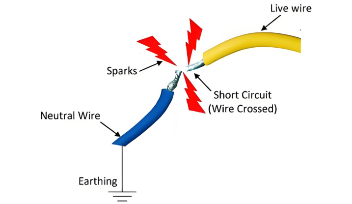
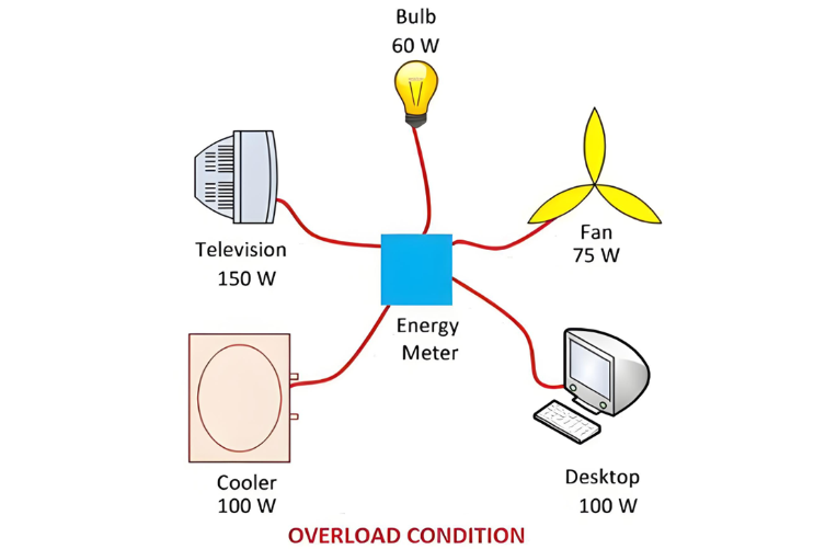
One of the main differences between a short circuit and an overload is that a short circuit occurs due to a fault between conductors (line-to-line) or between a conductor and earth (line-to-ground), whereas an overload refers to a situation where equipment draws more current than its rated capacity from the power supply.

Other key differences between the two are explained in the comparison chart below.

The term "overload" typically refers to a condition in a circuit or connected device. A circuit is considered overloaded when the connected load exceeds its designed capacity. Overloads usually result from equipment malfunction or faulty circuit design. In contrast, a short-circuit condition arises when bare metal conductors come into direct contact with each other, or when insulation between conductors fails. During a short circuit, the resistance drops nearly to zero, causing an extremely high current to flow through the network.

Definition of Short Circuit

A short circuit is an electrical fault that allows current to flow along an unintended path with very low (or negligible) resistance. This results in a massive surge of current that can severely damage the insulation and components of electrical equipment. Short circuits commonly occur when two live conductors touch each other or when the insulation between conductors breaks down.

The magnitude of short-circuit current can be thousands of times greater than the normal operating current. At the fault point, the voltage drops to nearly zero, while a very high current flows through the system.

Short circuits have several harmful effects on power systems, including:

  • Excessive heat generation: The heavy fault current produces intense heat, which may lead to fires or even explosions.
  • Arcing damage: The formation of electric arcs during a short circuit can cause severe damage to power system components.
  • System instability: Short circuits can disrupt the stability of the power network, affecting the continuity and reliability of power supply.

Definition of Overload

An overload occurs when a load greater than the designed or rated capacity is imposed on a power system or equipment. During an overload, the voltage drops significantly but does not fall to zero. The current increases beyond normal levels, although it remains considerably lower than the current during a short circuit. This excessive current leads to increased heat generation, as described by Joule’s law (P = I²R), which raises the temperature of conductors and components. This overheating can cause insulation damage, equipment failure, or even fire hazards.

The overload condition can damage power system equipment. For example, consider an inverter rated at 400 watts: connecting an 800-watt load to it will cause an overload, potentially leading to overheating and equipment failure.

Key Differences Between Short Circuit and Overload

  • A short circuit occurs when the voltage at the fault point drops to nearly zero, causing an extremely large current to flow through the circuit. In contrast, an overload happens when a load greater than the system’s designed or safe capacity is connected.

  • In a short circuit, the voltage at the fault location decreases to almost zero. In an overload condition, the voltage may drop due to excessive demand, but it does not fall to zero.

  • During a short circuit, the resistance of the current path becomes very low (nearly zero), resulting in a massive surge of current. In an overload, the current is higher than normal but significantly lower compared to short-circuit current.

  • A short circuit typically occurs when the live (phase) and neutral wires come into direct contact due to insulation failure or accidental bridging. An overload, on the other hand, occurs when too many electrical devices are connected to the same circuit or outlet, exceeding its rated capacity.

Short-circuit current is primarily supplied by synchronous machines, including synchronous generators, synchronous motors, and synchronous condensers.

The Electricity Encyclopedia is dedicated to accelerating the dissemination and application of electricity knowledge and adding impetus to the development and innovation of the electricity industry.

Difference Between Leading and Lagging Power Factor
Leading and lagging power factors are two key concepts related to the power factor in AC electrical systems. The main difference lies in the phase relationship between current and voltage: in a leading power factor, the current leads the voltage, whereas in a lagging power factor, the current lags behind the voltage. This behavior depends on the nature of the load in the circuit.What is Power Factor?Power factor is a crucial, dimensionless parameter in AC electrical systems, applicable to both s
08/26/2025
Difference Between Electromagnet and Permanent Magnet
Electromagnets vs. Permanent Magnets: Understanding the Key DifferencesElectromagnets and permanent magnets are the two primary types of materials that exhibit magnetic properties. While both generate magnetic fields, they differ fundamentally in how these fields are produced.An electromagnet generates a magnetic field only when an electric current flows through it. In contrast, a permanent magnet inherently produces its own persistent magnetic field once it has been magnetized, without requirin
08/26/2025
Interpretation of the “Five Mandatory Surveys” for On - site Investigation in the Operation and Maintenance Specialty
The power outage and work scopes must be clearly inspectedCollaborate with the site survey leader to confirm the equipment to be maintained and the work area involved. Consider requirements such as the use of special vehicles and large machinery, and safe distances from adjacent energized equipment. Verify on-site whether the proposed power outage scope is sufficient to meet the operational needs.On-site safety measures must be clearly inspectedCollaborate with the site survey leader to verify s
Vziman
08/14/2025
Plugging or Reverse Current Braking
In plugging or reverse current braking, the armature terminals or the supply polarity of a separately excited or shunt DC motor is reversed while the motor is running. As a result, during plugging, the supply voltage V and the induced armature voltage Eb (also known as back EMF) act in the same direction. This causes the effective voltage across the armature circuit to become (V + Eb), nearly twice the supply voltage. The armature current reverses, producing a high braking torque. To limit the a
08/14/2025
Inquiry
Download
IEE-Business is dedicated to serving the personnel in the global power industry.
Join IEE-Business, not only can you discover power equipment and power knowledge, but also canhnd like - minded friends!