1. Industry Background & Pain Point Analysis
1.1 Industry Background
Overseas industrial parks, islands, and commercial and industrial users increasingly demand energy that is "self-generated, self-consumed, low-carbon, and reliable." Traditional AC microgrids suffer from multi-stage AC/DC conversion losses, complex grid-connected/islanded switching, and difficulties integrating multiple energy sources (PV, storage, charging, hydrogen). DC microgrids, which use a common DC bus to unify diverse energy carriers, have become the mainstream technical route for zero-carbon parks.
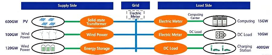
1.2 Four Major Pain Points of Traditional AC Microgrids
1.3 Core Differences: Traditional AC vs. SST DC Microgrid (Physical Essence)
| Aspect |
Traditional AC Microgrid (Physical Principle) |
SST DC Microgrid (Physical Principle) |
| PV integration |
DC→AC inversion, single conversion loss 1%–3% |
PV directly connected to DC bus, zero conversion |
| Storage integration |
DC→AC→DC bidirectional conversion, cumulative losses |
Storage directly connected to DC bus, bidirectional and efficient |
| Load supply |
AC→DC multi-stage conversion |
DC loads (charging, hydrogen, etc.) directly connected nearby |
| Grid/island switching |
Requires triple synchronization; switching risks interruption |
DC networking inherently isolated; smooth power-controlled switching (<20 ms) |
Physical root cause: The DC bus enables PV, storage, charging, and hydrogen to couple directly in DC, avoiding multiple AC/DC conversions—this is the fundamental physical basis for overall microgrid efficiency improvement and the first-principle differentiator of this solution over traditional approaches.
2. Solution Overview & Value Proposition
2.1 Solution Definition (BLUF)
This solution features the SST solid-state transformer as the core and a 10+1-port DC router as the backbone, building a "PV-Storage-Charging-Hydrogen direct-flexible" commercial complex DC microgrid: PV, storage, charging, hydrogen, and building loads flexibly access a unified DC bus, with only one AC conversion at the grid interface. Overall plant efficiency reaches 94.5%–97.5% (3–5 percentage points higher than AC solutions), with grid/island switching <20 ms.
Benchmark project: Amsterdam, Netherlands — "PV-Storage-Charging-Hydrogen direct-flexible" commercial complex demonstration project (one of Europe's first, 10+1-port DC networking).
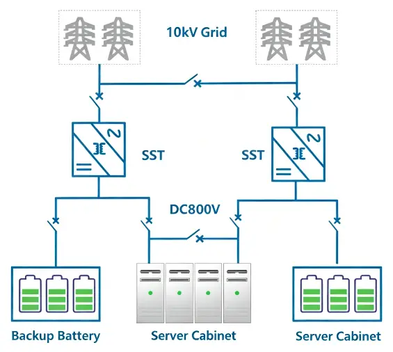
2.2 Core Value Proposition
3. System Architecture Design
3.1 System Topology (Layered Breakdown)
SST DC Router (10+1 ports) Port Planning:
-
Source ports: PV input (DC), storage (DC), grid connection (AC — the sole AC interface)
-
Load ports: Charging piles (DC), hydrogen production (DC), building loads (DC/AC optional)
-
Routing core: SST DC router with full-port power controllability
-
Management layer: EMS (Energy Management System) + microgrid controller for unified scheduling and black-start management
3.2 Seamless Grid/Island Switching Principle
Inherent isolation via DC networking: The SST router implements smooth mode switching through cascaded control of power outer loop and voltage inner loop, with switching time <20 ms (within one cycle), no transient impact, and no downtime. In island mode, the storage provides bus voltage support; in grid-connected mode, the grid interface maintains power balance. This capability is the core reliability enabler for overseas island and park applications.
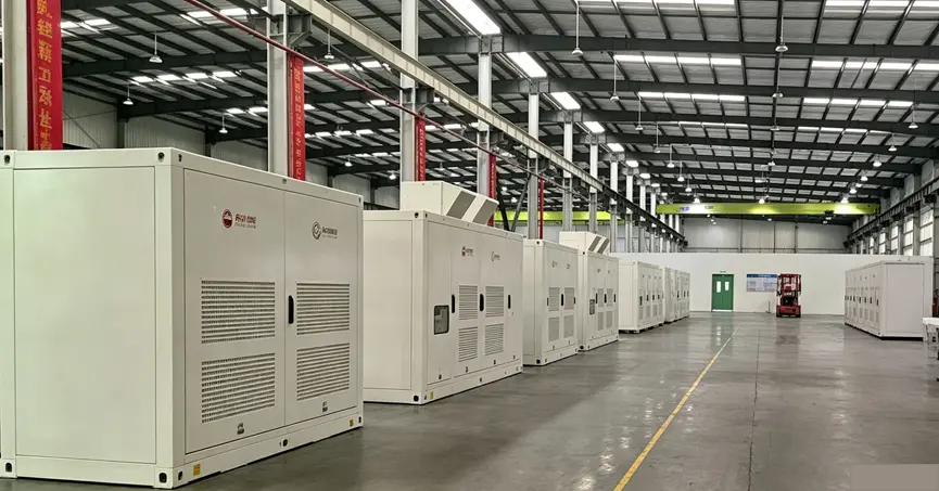
4. Core Equipment & Technical Parameters
SST DC Router Core Parameters (10+1 ports, series configurations):
5. Technical Highlights & In-Depth Physical Principle Analysis
5.1 Highlight 1: Multi-Port DC Networking
Physical principle: PV, storage, charging, and hydrogen are directly DC-coupled through the SST router's multiple ports, eliminating multiple conversions.
Quantified benefit: Source-load direct connection eliminates 2–4 conversion stages; overall efficiency 94.5%–97.5%, 3–5 p.p. higher than AC solutions; THD <1%, no additional filtering required.
5.2 Highlight 2: Seamless Grid/Island Switching
Physical principle: Inherent DC bus isolation, plus power-voltage cascaded control, enables transient-free switching.
Quantified benefit: Switching time <20 ms (within one cycle); reliable in both island and grid-connected modes; no downtime or power interruption during transitions.
5.3 Highlight 3: Multi-Energy Integration & Plug-and-Play
Physical principle: PV, storage, charging, and hydrogen are unified on a single DC bus with modular ports.
Quantified benefit: Simplified system and easy expansion—new sources/loads connect plug-and-play; capacity scales modularly; single-port faults are rapidly bypassed via N+X redundancy, ensuring availability ≥99.9%.
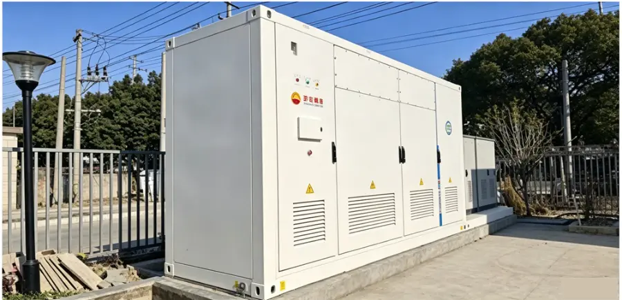
6. Economic Comparison with Traditional Solutions
| Cost Item |
Traditional AC Microgrid |
SST DC Microgrid |
Difference |
| Conversion losses |
Multi-stage cumulative 2%–6% |
Only one grid-interface conversion (1%–3%) |
Overall efficiency +3–5 p.p. |
| Equipment investment |
Distributed inverters, filters, transformers |
Integrated DC router; eliminates separate inverters/filtering |
Lower initial investment |
| Footprint |
Multiple equipment rooms + filtering/cooling space |
Volumetric power density 0.66 kW/dm³; reduced footprint |
Lower civil construction costs |
| O&M |
Distributed equipment, more spares, broader inspection scope |
Centralized monitoring + full-lifecycle remote O&M |
Lower O&M costs |
Note: Loss figures are based on "single AC/DC conversion 1%–3% (typical for SiC inverters); traditional multi-stage cumulative 2%–6%." Detailed economics should be calculated based on project scale, local electricity tariffs, and construction costs.
7. Benchmark Project Evidence
| Project |
Key Data |
Significance |
| Amsterdam, Netherlands (overseas microgrid) |
10+1-port PV-storage-charging-hydrogen direct-flexible commercial complex (one of Europe's first demonstrators) |
Overseas DC microgrid benchmark; specific capacity/bus voltage per project contract |
| Kunshan, China (CNPC reference) |
SST ultra-fast hybrid charging station: efficiency 95%+, footprint –40% |
SST charging-scenario engineering validation |
| Chongqing Shuitu, China (GDS reference) |
10 kV direct-connected storage: overall efficiency 90%, SOC balancing 99% |
Medium-voltage direct-connected storage engineering validation |
Evidence chain note: "One of Europe's first" is based on public-case references; bidding stage can provide project commissioning date, system capacity, and third-party test reports for substantiation.

8. Technical Standards, Redundancy & Safety
8.1 Technical Standards & Compliance
8.2 Redundancy Architecture
N+X intelligent online redundancy: dual power supplies + dual-controller hot standby; faulty IGBT auto-bypass; single-port faults do not propagate; system availability ≥99.9%.
8.3 DC Safety
DC arcs have no natural zero-crossing and are persistent—the solution deploys three defense lines: ① Fast solid-state isolation logic per IEC 60947-2 Annex P (arc clearing time <25 μs); ② DC-side insulation online monitoring (real-time insulation resistance/leakage current alarms); ③ Port-level fault isolation and fast arc extinction to prevent single-point fault propagation. Overseas project delivery includes a safety design description and protection setting scheme.
9. Delivery & Services
-
Modular DC router: Factory prefabricated, complete-unit shipment, and rapid on-site installation;
-
Overseas localized delivery: Supports destination-country standard adaptation and local certification assistance;
-
Full-lifecycle remote O&M: EMS cloud monitoring + OTA upgrades + fault self-diagnosis + SOH online assessment.

 Login