• Product
  • Suppliers
  • Manufacturers
  • Solutions
  • Free tools
  • Knowledges
  • Experts
  • Communities
Search


Smart Meter Solution Based on Low-Voltage Power Line Carrier

Wone Store
2yrs + staff 1000+m² US$300,000,000+ China

  1. Design Background and Core Positioning
  1. Technical and Market Background
    With the rapid development of computer technology, microelectronics, and communication technology, low-voltage power line carrier (220V) technology has matured and established a dominant position in the field of automatic meter reading systems. In contrast, high-voltage power lines, due to multiple interference factors and high implementation costs, have not achieved large-scale applications similar to fiber optics or satellite communication.
  2. System Positioning
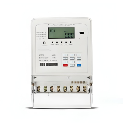
    The smart meter designed in this solution serves as the core underlying unit of a multifunctional low-voltage power line carrier remote meter reading system. It works in coordination with data concentrators and backend management systems, aiming to replace manual meter reading in various scenarios such as low-voltage residential users, large consumers (key users), and substations, ultimately achieving full automation and intelligence in electricity management.

II. Smart Meter Hardware Design

  1. Overall Hardware Architecture
    The system hardware is centered around a microprocessing unit (MCU), integrated with supporting modules such as a watchdog, data storage, power-off detection, energy conversion, carrier communication, display unit, relay control, and meter power supply. Each module collaborates to ensure stable and reliable operation of the meter. (Refer to Figure 1 in the original document for the structural diagram.)
  2. Key Hardware Module Details
    | Hardware Module | Core Component / Specification | Main Function |
    |---------------------------|--------------------------------------|-------------------------------------------------------------------------------|
    | Control Unit (MCU) | AT89C2051 microcontroller | Processes metering data (calculation, storage); responds to concentrator commands (uploading energy data, executing power on/off); controls display. |
    | Energy Conversion Circuit | AD7755 high-precision integrated chip| Converts user-consumed energy (kW·h) into digital pulses processable by the MCU; a core feature of electronic meters. |
    | Carrier Communication Module | - | Connects to the power line via a coupling circuit; modulates and demodulates digital and analog signals for bidirectional data transmission. |
    | Display Unit | - | Displays energy consumption, time, usage periods (peak/flat/valley), tariff rates, etc., driven by software. |
    | Relay | - | Receives MCU commands; remains closed during normal operation, executes power-off in case of unpaid fees or remote commands for electricity management. |
    | Data Storage | 24CoX series storage chip | Stores critical data (e.g., energy consumption) during power outages; supports power-off preservation, long storage time, and uses I2C read/write method. |
    | Meter Power Supply | - | Provides stable power to all hardware circuits, including the MCU, communication module, and display unit. |
    | Power-Off Detection & Watchdog | - | Power-off detection: Monitors voltage and triggers data protection during abnormalities; Watchdog: Prevents program deadlocks and enables system auto-reset. |
  3. Meter Working Principle
    • ​Energy Metering: User energy consumption is converted into digital pulses by the AD7755 chip. The MCU counts a specific number of pulses as 1 kW·h based on preset parameters and accumulates and stores them according to peak, flat, and valley periods.
    • ​Data Interaction: The data concentrator issues meter reading or control commands. The meter uploads stored energy data via the carrier module over the power line. If a power-off command is received, the MCU immediately controls the relay to execute the power-off operation.
    • ​Exception Protection: The power-off detection circuit notifies the MCU to quickly transfer critical data to the 24CoX chip when power abnormalities are detected. The watchdog module forces a system reset in case of program malfunctions, ensuring reliability.

III. Smart Meter Software Design

  1. Programming Approach and Core Objectives
    A mix of assembly language and C language is used for programming, balancing program efficiency and development flexibility. The core objectives are to automate and intelligentize the meter’s functions while minimizing the MCU’s storage usage.
  2. Main Program Modules
    • ​Data Acquisition and Processing Module: Collects energy pulses, calculates total user energy consumption, and categorizes statistics by period (peak/flat/valley).
    • ​Communication Interaction Module: Enables bidirectional communication with the concentrator, including clock synchronization, uploading real-time/monthly energy data, and receiving and executing relay commands (e.g., power on/off control).
    • ​Protection and Exception Handling Module: Integrates software watchdog, reliable power-on determination (preventing data corruption), power-off detection, and data processing, working with hardware to ensure system stability.
    • ​Time Period and Tariff Management Module: Sets period rules for multi-tariff applications, determines the current period in real-time, and provides a basis for differentiated metering.
    • ​Display Control Module: Drives the display unit to show energy consumption, time, tariff rates, and other information as needed, ensuring intuitive data visualization.
  3. Software Main Program Flow
    After system startup, a "reliable power-on" determination is performed→parameters are initialized or historical data is read based on the determination result→time intervals are set and the current usage period is determined→whether it is the meter reading day is checked and data is prepared→power-off is detected in real-time and protection is triggered→carrier commands are detected and communication processing is executed→intervals are reset, and the cycle repeats. (Refer to Figure 2 in the original document for the detailed flow.)

IV. Remote Metering System and Application Prospects

  1. System Composition and Functions
    The complete remote metering system consists of three parts:
    • ​Smart Meter: Responsible for terminal metering and command execution.
    • ​Data Concentrator: Responsible for intermediate data aggregation and command distribution.
    • ​Backend Management System: Responsible for data statistics, analysis, line loss calculation, exception alerts, and report generation.
    The core function of the system is to achieve full automation from energy collection→data transmission→statistical queries→line loss analysis→exception alerts→report generation, completely replacing manual meter reading.
  2. Advantages and Prospects
    Compared to wireless or dedicated line solutions, this system leverages existing power lines, offering low investment costs, ease of maintenance, and significant potential for widespread adoption. It lays a solid technical foundation for future smart communities to achieve "remote transmission of three meters" (electricity, water, gas) and can further integrate with banking systems for automatic electricity fee deduction, greatly enhancing residential convenience.
  3. Future Challenges
    • ​Technical Level: Continuous improvement in meter data retrieval rates (ensuring successful data transmission) and optimization of relay algorithms to enhance communication stability in complex power line environments.
    • ​Application Level: Adapting to power reform trends, promoting deeper integration of the system with advanced management functions such as load regulation and energy-saving analysis.
09/03/2025
Recommended
Solution for Medium-Voltage Motor Control and Protection Using Vacuum Contactor-Fuse (VCF) in a Coal Conveying System
Project BackgroundA coal conveying system comprises 15 belt conveyors driven by medium-voltage motors. The system operates under complex conditions, with motors often subjected to heavy loads and frequent starts. To address these challenges and achieve effective control and reliable protection during motor startup, the project comprehensively adopts Vacuum Contactor-Fuse (VCF) combination devices for the 6kV medium-voltage motor power distribution. This solution details the technical features,
ABB Vacuum Contactor KC2 Power Supply System Technical Transformation Plan
Issue Overview​The 10kV air compressor starting system of a company utilizes the ABB vacuum contactor KC2 as the control component for the operating circuit. The dedicated wide-voltage power supply module paired with this contactor presents the following issues:​Frequent failures: The power supply module fails to properly transition the voltage from 300V to 12V, resulting in fuse blowouts.​Poor heat dissipation: Enclosed installation of the module leads to insufficient heat dissipation, acceler
Dedicated Vacuum Contactor Solution for Port Shore Power Systems
I. Background and Challenges​Shore power systems have become core technical equipment for ports to reduce carbon emissions and noise pollution. However, these systems face two major challenges in the harsh operational environment of ports:​Severe Environmental Corrosion: High humidity and salt spray in port areas cause serious corrosion to metal components and enclosures of electrical equipment, significantly impacting electrical lifespan and operational reliability.​High Switching Requirements:
Vacuum Contactor Industrial Power Control Solutions
Application Background and Pain Point Analysis​In modern industrial manufacturing power control systems, traditional contactors exhibit significant limitations under specific operating conditions:• ​Frequent Start-Stop Operations: Traditional contactors have limited mechanical lifespan, with frequent operations leading to coil burnout and mechanical jamming.• ​Poor Adaptability to Harsh Environments: Contacts are prone to oxidation in dusty environments, resulting in increased contact
Seed Inquiry
Download
Get the IEE Business Application
Use the IEE-Business app to find equipment, obtain solutions, connect with experts, and participate in industry collaboration anytime, anywhere—fully supporting the development of your power projects and business.