I. Gwọrọ Ụzọ
Ụzọ a na-eme ka gbanwee ike inye ụzọ ezi eme n'okpuru FC site na "High-Voltage Vacuum Contactors + High-Voltage Current-Limiting Fuses". Ọ bụkwa site n'ịkpeazụ na ịgbakwunye obere mgbochi ọnụ oyi, ụdị okpuru ọhụrụ, na ụdị capacitor banks n'okpuru 3kV ruo 12kV, dị ka ọ ga-enyere mmadụ maka ndepụta na mkpa ( dịka power plants, ụlọ ọrụ ndị kachasị, na mines). Nke a bụ ihe dị mkpa n'ebe a bụ ọtụtụ n'ime vacuum contactor na fuse current-limiting, enweghị ezi eme n'okpuru overload na short-circuit faults, ma bụghị nwere ọrụ dị elu, ọma, na akụkọ.
II. Otu Na-ekwu Ihe Technical Characteristics
1. High-Voltage Vacuum Contactor (FC Circuit Operation and Overload Interruption Component)
High-voltage vacuum contactor bụ onye na-egosi ọrụ n'okpuru nke ọtụtụ nke ọrụ na ịkpeazụ overload currents. Ụfọdụ ihe dị ka:
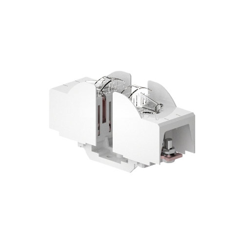
- Core Structure:
- Vacuum Interrupter Chamber: Enweghị ceramic enclosure na vacuum degree nke dị elu dị ka 1.33×10⁻⁴ Pa, nke na-enye ọrụ na ịkpọta arc n'ụbọchị a bụrụ na current zero-crossing, enweghị oil na ọrụ ọmụmụ.
- Insulation Mounting Bracket and Interlocking Mechanism: Integrate fuse mounts na-enweghị interlocking trip mechanism. Mechanism a na-enye: ① Bụrụ na fuse n'ụdị phase kọrọ, ọ na-enye three-phase simultaneous trip nke contactor, ịkpọta single-phasing operation; ② Bụrụ na fuse n'ụdị phase adịghị, ọ na-enye mechanical lock nke contactor n'ịgbanwe, nkwado ọrụ ọmụmụ.
- Operating Mechanism: Enweghị electromagnetic mechanism, na-enye ọrụ ọtụtụ nke ọrụ n'otu otu nke ọtụtụ nke ọrụ 2000 times/hour, dị elu nke ọrụ circuit breakers.
- Operation and Interruption Principle:
- Interruption Principle: Enweghị high insulation na strong arc-extinguishing capability nke vacuum medium. Metal vapor arc nke ọrụ n'ịgbanwe na-enye ịkpọta instantaneously n'ụbọchị a bụrụ na current zero-crossing point, na-enye rapid dielectric strength recovery. Chopping current ya bụ nke dị elu 0.5A, na-enye suppression nke switching overvoltages, nke ọ dị ọma maka motor insulation.
- Holding Method: Enweghị electrical self-hold (energy-saving, low noise) na mechanical self-hold (high reliability, anti-interference) methods. Users na-enye ọrụ maka operational requirements (e.g., LHJCZR series na-enweghị mechanical self-hold).
- Key Rated Parameters:
|
Parameter Category
|
Specific Indicator
|
|
Rated Voltage
|
3.6 / 7.2 / 12 kV
|
|
Rated Operational Current
|
200 / 400 / 630 A
|
|
Rated Breaking Capacity
|
3.2 kA (25 times)
|
|
Ultimate Breaking Capacity
|
4 kA (3 times)
|
|
Rated Making Capacity
|
4 kA (100 times)
|
|
Peak Withstand Current
|
40 kA
|
|
Mechanical/Electrical Life
|
1,000,000 cycles / 300,000 cycles
|
2. High-Voltage Current-Limiting Fuse (FC Circuit Short-Circuit Protection Component)
High-voltage current-limiting fuse bụ nke na-ekwu ụzọ ụdị short-circuit faults. Ụfọdụ ihe dị ka:
- Core Function: Enweghị instantaneous (quick-break) protection. Bụrụ na severe short-circuit fault na-eme (current exceeding the contactor's breaking capacity), fusible element ya na-enye ịkpọta na ịkpeazụ okpuru n'ụbọchị a bụrụ na current na-eme n'ịkpeazụ nke prospective peak. Ịkpeazụ time ya bụ nke dị elu (millisecond level), na-enye limitation nke fault current energy n'ọtụtụ, nkwado ụdị downstream equipment nke ọrụ.
- Basic Selection Principles:
- Rated Voltage: Adịghị ịkọnye system's rated voltage, ịkpọta overvoltage nke na-eme n'fuse operation nke ọ dị elu insulation withstand level (typically limited to below 2.5 times the phase voltage).
- Rated Current: Nwere ọrụ comprehensive consideration nke normal/overload currents, ụdị starting inrush characteristics (e.g., motor starting current, transformer magnetizing inrush), na ensuring selective coordination nke upstream protective devices (e.g., relays).
- Role Positioning: Enweghị ụzọ ụdị backup protection n'okpuru FC. Normal overloads na smaller short-circuit currents na-enye comprehensive protection device signaling nke vacuum contactor n'ịkpeazụ. Fuse na-eme ọrụ n'ọtụtụ na fault current exceeding the contactor's breaking capacity ma ọ bụ contactor adịghị ịkpeazụ.
III. Selection Guidance Based on Protected Object
1. Motor Protection Fuse Selection
Motor starting currents bụ nke dị elu na durations long, na-enye ọrụ extra caution n'ịkpeazụ ịkpọta nuisance operation.
- Protection Coordination Logic:
- Overload Protection (e.g., stall, repeated starting): Implemented by inverse-time relays, driving the contactor to open.
- Short-Circuit Protection: Implemented by the fuse.
- Coordination Requirement: The fuse's rated current must be greater than the motor's starting current, and its time-current characteristic curve must intersect the relay's curve at one point to achieve perfect coordination.
- Selection Reference (Excerpt):
|
Motor Power (kW)
|
Starting Time (s)
|
Starting Current (A)
|
Fuse Link Rated Current (A) at Different Starting Frequencies (times/h)
|
|
250
|
6
|
220
|
100A (2/3/4 times) -> 105A (8/16/32 times)
|
|
250
|
15
|
200
|
100A (2/3 times) -> 125A (4/8/16/32 times)
|
|
800
|
60
|
600
|
250A (2 times) -> 315A (3/4/8/16/32 times)
|
- Key Point: The longer the starting time and the higher the starting frequency, the larger the required fuse link rated current.
2. Transformer Protection Fuse Selection
Selection must ensure the fuse can withstand the transformer's closing magnetizing inrush current while providing effective protection against internal faults.
- Selection Reference (Excerpt):
|
System Voltage (kV)
|
Transformer Capacity (kVA) and Recommended Fuse Rated Current (A)
|
|
3.6
|
100-160kVA: 63A
|
|
7.2
|
100-160kVA: 50A
|
|
12
|
100-160kVA: 31.5-40A
|
3. Capacitor Bank Protection Fuse Selection
Capacitor bank switching generates high-frequency, high-amplitude closing inrush currents, posing special requirements for fuse selection.
- Special Consideration: Must verify that the fuse can withstand the let-through energy (I²t) of the closing inrush current. Requirement: Inrush let-through energy < 0.7 times the fuse's minimum pre-arcing energy.
- Selection Requirements:
- Rated current is typically 1.5~2.0 times the capacitor's rated current.
- If the inrush current is too large, consider: ① Selecting dedicated capacitor fuses (e.g., WFN series); ② Adding a series current-limiting reactor with the capacitor; ③ Adding a series damping resistor in the branch.
- Recommendation: A current-limiting reactor must be used when (Inrush Peak Current * Inrush Frequency) > 20000 or during extremely frequent operations.
IV. Application Scope and Typical Cases
1. Application Scope
The FC circuit solution is not universal. Its applicable boundaries are as follows:
- High-Voltage Motors: ≤ 1200 kW
- Distribution Transformers: ≤ 1600 kVA
- Capacitor Banks: ≤ 1200 kvar
Beyond these capacity ranges, a vacuum circuit breaker solution with higher breaking capacity and dynamic/thermal stability must be selected to ensure safety.
2. Typical Case Validation
This solution has been successfully applied in multiple projects, operating stably and reliably:
- Case 1: Chemical Plant, Texas, USA (Frequent Operation and Explosion-Proof Environment)
- Project Overview: This large chemical base required frequent start-stop control for high-voltage pumps and compressor motors across multiple production lines, with environmental requirements for explosion-proofing and high reliability.
- Advantages Demonstrated: The contactor's 2000 operations/hour frequency perfectly met process adjustment needs; precise coordination between the fuse and relay ensured accurate short-circuit protection for motors under frequent starting without nuisance operation; the low chopping current (<0.5A) provided by the vacuum interrupter effectively suppressed switching overvoltages, protecting the insulation of older motors. The overall solution saved significant investment compared to vacuum circuit breaker switchgear.
- Case 2: Automotive Manufacturing Plant, Bavaria, Germany (Transformer and Capacitor Compensation Protection)
- Project Overview: A new smart manufacturing factory required stable, high-quality power supply for numerous robotic servo systems on automated production lines, accompanied by multiple dry-type distribution transformers and capacitor compensation banks.
- Advantages Demonstrated: Fuse rated current selection fully considered transformer magnetizing inrush characteristics, avoiding nuisance operation during closing. For the capacitor banks, dedicated fuses successfully withstood the closing inrush impact (I²t verification passed). The contactor's low bounce ensured capacitor switching without re-ignition, safeguarding power quality on the grid.
V. Solution Advantage Summary
- High Reliability: Vacuum interrupter chamber is maintenance-free with a mechanical life of up to millions of operations; fuses provide millisecond-level quick-break protection.
- Strong Safety: Mechanical interlocking mechanism prevents single-phasing operation and closing with potential hazards; low chopping current protects equipment insulation.
- Good Economy: Compared to vacuum circuit breaker switchgear, FC switchgear offers lower cost, smaller size, and extremely high cost-effectiveness.
- Intelligence: Contactors can be seamlessly integrated with microprocessor-based protection devices, enabling remote monitoring, intelligent control, and data upload.
- Easy Maintenance: Core components are designed for maintenance-free operation; after fuse operation, only replacement with a same-specification fuse link is required, making operation simple.


