- Application Challenge: Bottlenecks of Traditional Short-Circuit Protection Schemes
In modern power grids, particularly in substations of power plants and large industrial parks, the parallel operation of multiple transformers or generators is widely adopted to enhance power supply reliability and energy efficiency. However, this leads to a sharp increase in system short-circuit current levels, often exceeding the rated withstand capacity (e.g., dynamic/thermal withstand current) of existing equipment such as switchgear, circuit breakers, and transformers.
Traditional solutions face significant challenges:
- Traditional Circuit Breakers: Their breaking time spans tens of milliseconds, unable to prevent the impact of the first short-circuit current peak (peak current). Equipment still endures enormous electromagnetic force and thermal effects, posing a risk of damage.
- Current Limiting Reactors: While they can limit short-circuit current, their permanent series operation results in continuous active power losses (increased electricity costs), voltage drops (affecting power quality), and reactive power losses. They may also cause issues with generator regulation, offering poor economic and technical performance.
- Complete Equipment Replacement: Replacing entire switchgear sections or transformers to cope with increased short-circuit currents requires massive investment, involves complex engineering, and causes prolonged power outages.
II. Solution: Core Application Value of the Ultra-Fast Current Limiter (FCL)
The Ultra-Fast Current Limiter (FCL) provided in this solution is an intelligent device based on a parallel configuration of a "fast switch" and a "current-limiting fuse." It fundamentally addresses the aforementioned challenges, with its core application value lying in "millisecond-level breaking" and "full lifecycle economic benefits."
Core Application Advantages:
- Ultra-Fast Protection, Eliminating Peak Current Impact: Capable of completing detection and current limiting action within 1 millisecond after a short circuit occurs, effectively limiting the current before it reaches its destructive peak. This perfectly protects equipment like switchgear, CTs, and cable joints from immense electromagnetic forces, which is unachievable with traditional circuit breakers.
- Significant Economic Benefits and Energy Savings: The FCL is typically applied in parallel with a current-limiting reactor. During normal operation, current flows through the FCL (near-zero loss); during a short circuit, the FCL rapidly breaks, and current is transferred to the reactor for limiting. This mode avoids the substantial electricity cost losses associated with the long-term operation of reactors, making it the most economical current limiting solution. Simultaneously, it avoids the prohibitively expensive investment of replacing entire switchgear sections, significantly reducing the cost of substation retrofitting, expansion, or new construction.
- High Reliability and Maintenance-Free Design: Proven stable performance through over 60 years of global operation. Its core actuating component, the conductive bridge, features a modular design. After operation, only the internal module needs factory replacement, resulting in very low maintenance costs, and the main structure is reusable.
- Broad Scenario Adaptability: It is the only or optimal technical solution for addressing excessive short-circuit currents in scenarios such as parallel operation of multiple transformers and grid connections with captive power sources.
III. Typical Application Scenarios and Solutions
|
Application Scenario
|
Core Problem
|
FCL Solution
|
|
1. Bus Sectionalizing / Transformer Parallel Operation
|
Parallel operation of multiple transformers causes short-circuit current to far exceed levels under single transformer operation, surpassing the withstand limit of switchgear (e.g., cabinet withstands 2Ik, 4 parallel units can reach 4Ik).
|
Install FCL at the bus sectionalizing point (e.g., between sections 1-2 and 3-4). Ensures bus tie during normal operation; rapidly breaks during faults, limiting short-circuit current to an acceptable system level without replacing switchgear.
|
|
2. Bypassing Current Limiting Reactors
|
Existing reactors cause high energy consumption and voltage drop during long-term operation.
|
Connect the FCL in parallel with the reactor. During normal operation, the FCL conducts, bypassing the reactor for zero loss and zero voltage drop; during a short circuit, the FCL breaks, transferring current to the reactor for limiting.
|
|
3. Grid and Captive Power Source Connection Point
|
Commissioning of captive generators within an enterprise can cause short-circuit current at the Point of Common Coupling (PCC) to exceed limits, threatening upstream grid equipment.
|
Installing an FCL at the connection point is the only reasonable solution. Directional protection functionality can be added to ensure operation only for grid-side faults, avoiding maloperation.
|
|
4. Power Plant or Large Factory Feeders
|
The large short-circuit capacity of auxiliary power systems makes it difficult for outgoing feeder equipment to withstand.
|
Install FCLs on feeder circuits at the generator or transformer outlet to provide top-level protection for downstream switchgear, enhancing overall system security.
|
IV. Technical Implementation and Selection Guide
- Working Principle Brief Analysis:
The device monitors current (I) and its rate of change (di/dt) in real-time via high-precision bushing CTs. It employs dual criteria – only issuing a trip command when both exceed thresholds – effectively preventing maloperation. Upon triggering, the conductive bridge ruptures and breaks within 1ms, transferring current to the parallel special current-limiting fuse, which completes the current limiting and final arc extinguishing within an extremely short time.
- Supply Models and Selection:
Three integration modes are available flexibly based on project needs:
- Discrete Component Type: Suitable for retrofit projects, installed inside existing switchgear, saving space.
- Drawout Type (Truck Mounted): For new switchgear, the conductive bridge is installed on a withdrawable truck, also functioning as an isolating switch for convenient maintenance.
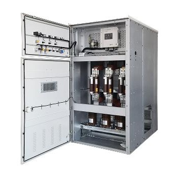
- Fixed Cabinet Type: Suitable for all voltage levels, especially 36/40.5kV systems. All components are fixedly installed in a compact structure.
- Key Selection Parameters (Example):
|
Technical Parameter
|
Unit
|
12kV / 17.5kV System
|
24kV System
|
36kV / 40.5kV System
|
|
Rated Voltage
|
kV
|
12 / 17.5
|
24
|
36 / 40.5
|
|
Rated Current
|
A
|
1250 - 5000¹
|
2500 - 4000¹
|
1250 - 3000¹
|
|
Maximum Breaking Capacity
|
kA (RMS)
|
210
|
210
|
140
|
|
Note ¹: Forced air cooling is required for rated currents exceeding 2000A.
|
|
|
|
|
V. Summary
The Ultra-Fast Current Limiter (FCL) is not merely a simple alternative device but represents a revolutionary approach to system protection. Through its millisecond-level breaking speed, it redefines the benchmark for short-circuit protection, delivering unprecedented safety and economic benefits to customers. When facing the widespread challenge of excessive short-circuit currents, the FCL provides a top-tier solution that is mature, reliable, and validated by thousands of projects globally. It is a strategic choice for ensuring the future reliability and economical operation of critical power systems.


