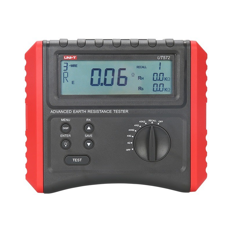
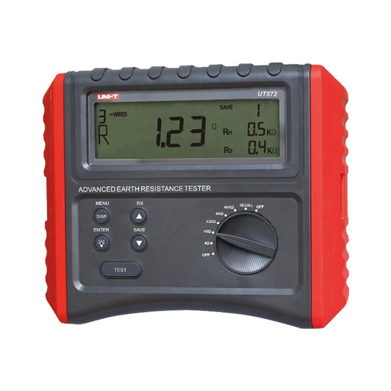
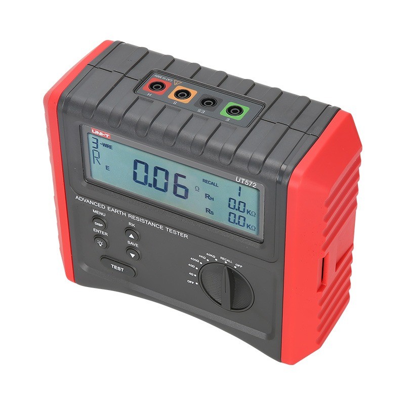
Advance Earth Resistance Tester Digital Ground Resistance Test/Soil Resistivity Test Data Storage LCD Backlight
Zhejiang Wone IT Service Co., Ltd.
1yrs 300++
staff 65666m²+m² US$50,000,000+
Key attributes
| Brand | Wone |
| Model NO. | UT572 Advance Earth Resistance Tester Digital Ground Resistance Test/Soil Resistivity Test Data Storage LCD Backlight |
| Earth resistance | 40kΩ ±(3%+5) |
| Soil resistivity | 40kΩm |
| Disturbance voltage | 50V DC/AC |
| Disturbance frequency | 40Hz~500Hz |
| Series | GR |
Product descriptions from the supplier
Description
Feature
Certifications: CE, UKCA
Large 4-digit LCD Display, 5s sampling time
2/3/4-wire earth resistance and soil resistivity measurements
Selectable test frequencies (94Hz/128Hz)
Disturbance voltage (Ust) and frequency (Fst) measurement
Earth resistance, RH and RS measurements
LCD backlight; auto power off
Data hold
20 sets of data storage
Double insulation
Compensating resistance RK measurement
Specifications


How are ground resistance and soil resistivity measured?

Wone
Zhejiang Wone IT Service Co., Ltd.
1yrs 300++
staff 65666m²+m² US$50,000,000+
Online store
On-time delivery rate
Response time
100.0%
≤4h
Company overview
Workplace: 65666m²m²
Total staff: 300+
Highest Annual Export(usD): 50,000,000
Services
Business Type: Design/Manufacture/Sales
Main Categories: High Voltage Electrical Apparatus/Low Voltage Electrical Apparatus/Wire cable/Instrument meters/New energy/Tester/Production equipment/Generator/Electrical fittings/Integrated Electrical Equipment
Whole life care manager
Full lifecycle management services for equipment procurement, use, maintenance, and after-sales,
ensuring safe operation of electrical equipment, continuous control, and worry-free electricity
consumption.
The equipment supplier has passed platform qualification certification and technical evaluation,
ensuring compliance, professionalism, and reliability from the source.
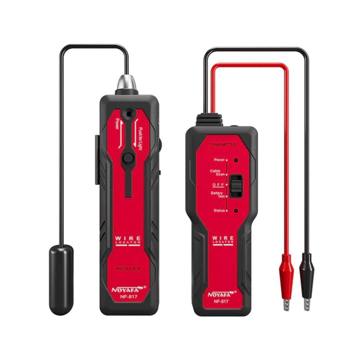
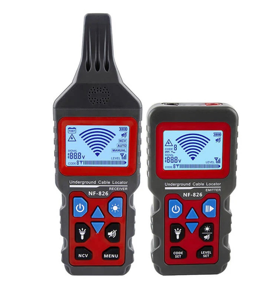
Related Products


Related Knowledges
-
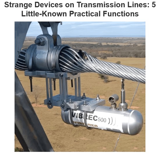 Strange Devices on Transmission Lines: 5 Little-Known Practical Functions(1)1 Aviation Warning SpheresAviation warning spheres, also known as reflective safety spheres, are used on overhead transmission lines near airports, especially on extra-high-voltage (above 220kV) lines and river-crossing transmission lines. Highly visible aviation marker spheres (aviation warning spheres) must be installed along the lines to provide warning signals.The aviation marker sphere (aviation warning sphere) has a diameter of ф=600mm. The sphere can be manufactured in various bright coloLeon09/04/2025
 -
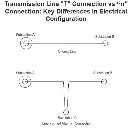 Transmission LineIn transmission lines, a "π" connection involves breaking the original line from Substation A to Substation B and inserting Substation C, forming a "π" configuration. After the "π" connection, the original single line is divided into two independent transmission lines. Following the "π" connection, Substations B and C may both be powered by Substation A (in this case, Substation C receives power via a feeder from Substation B's busbar, or possibly from another voltage point within Substation B);Encyclopedia09/04/2025
 -
 What are the principles of forced re-energization of transmission lines?Principles of Forced Re-energization of Transmission LinesRegulations for Forced Re-energization of Transmission Lines Correctly select the forced re-energization end of the line. If necessary, change the connection configuration before forced re-energization, taking into account the reduction of short-circuit capacity and its impact on grid stability. There must be a transformer with its neutral point directly grounded on the busbar at the forced re-energization end. Pay attention to the impactEdwiin09/04/2025
 -
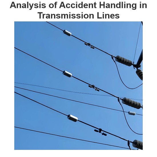 Analysis of Accident Handling in Transmission LinesAnalysis of Transmission Line Fault HandlingAs a fundamental component of the power grid, transmission lines are widely distributed and numerous, often exposed to diverse geographical and climatic conditions, making them highly susceptible to faults. Common causes include overvoltage, pollution flashover, insulation damage, tree encroachment, and external damage. Line tripping is one of the most frequent faults in power plant and substation operations, with fault types including single-phase-to-Leon09/04/2025
 -
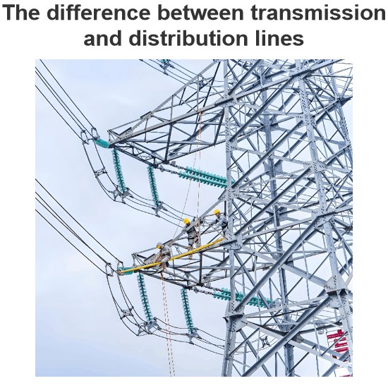 The difference between transmission and distribution linesTransmission lines and distribution lines are both used to carry electrical power from one location to another. However, they differ significantly in key aspects such as primary function, voltage levels, phase configuration, and conductor placement. These differences are essential for understanding their distinct roles in the power system.The Difference Between Transmission and Distribution Line is given below in the tabulated form.Electricity generation is a critical component of the power systEdwiin09/04/2025
 -
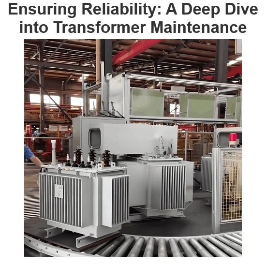 Ensuring Reliability: A Deep Dive into Transformer MaintenanceIntroductionElectric transformers are the backbone of modern power distribution systems, silently enabling the reliable delivery of electricity to homes, businesses, and industries. As these critical assets age and the demand for uninterrupted power grows, the importance of diligent transformer maintenance has never been greater. This essay explores the essential role of transformer maintenance, highlighting the value of proactive care, the impact of advanced diagnostic technologies, and the traVziman09/03/2025
Related Solutions
Haven't found the right supplier yet? Let matching verified suppliers find you.
Get Quotation Now


