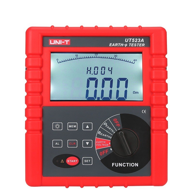
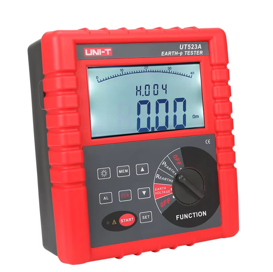
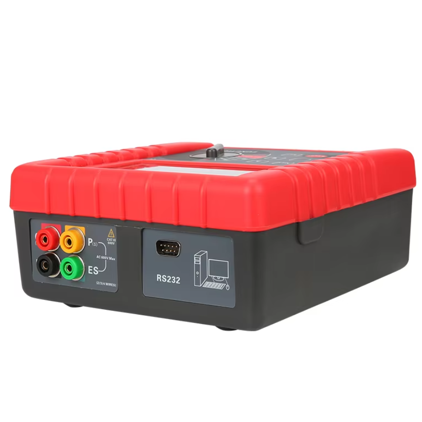
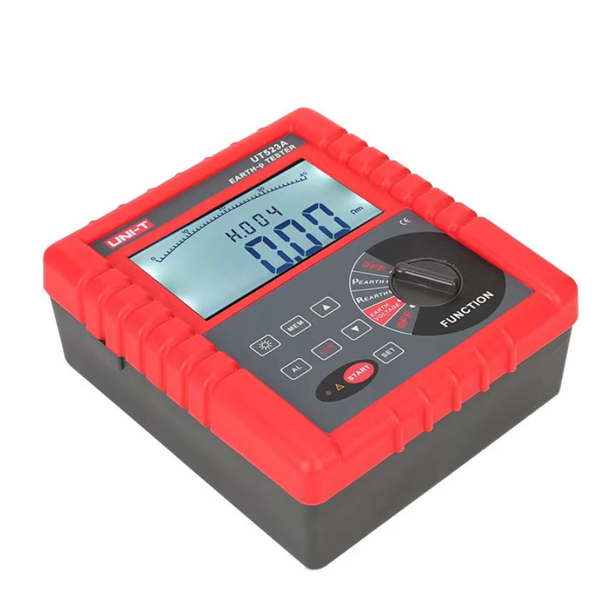
• Handheld Resistance Voltage Intelligent Grounding Resistance Tester Multi-Function Test Insulation Resistance Meter
  • Handheld Resistance Voltage Intelligent Grounding Resistance Tester Multi-Function Test Insulation Resistance Meter
  • Handheld Resistance Voltage Intelligent Grounding Resistance Tester Multi-Function Test Insulation Resistance Meter
  • Handheld Resistance Voltage Intelligent Grounding Resistance Tester Multi-Function Test Insulation Resistance Meter
Handheld Resistance Voltage Intelligent Grounding Resistance Tester Multi-Function Test Insulation Resistance Meter
$523.00
Model
GRM-210/9000
GRM-210/1000
GRM-210/100
GRM-210/10000
GRM-210/1000
GRM-210/100
GRM-20/100
GRM-20/1000
GRM-20/10000D
GRM-20/100D
GRM-20000/1000
GRM-20000/9000D
GRM-2000/9000D
GRM-2000/1000D-B
GRM-2000/100D-B
GRM-2000/10000D-B
GRM-2000/1000D-B
GRM-2000/100D-B
GRM-200/100D-B
GRM-200/1000D
GRM-200/10000D
GRM-200/100D
GRM-200/1000D
GRM-200/9000D
GRM-9000D-B
GRM-1000D-B
GRM-10000D-B
GRM-100D-B
GRM-20D-B
Basic info
Brand Wone
Model NO. UT523A Handheld Resistance Voltage Intelligent Grounding Resistance Tester Multi-Function Test Insulation Resistance Meter
Earth resistance 20.0kΩ~210.0kΩ
Soil resistivity 9000kΩm
Earth voltage AC 0.00~750V
Series GRM
Product Detail

Description

UT523A intelligent grounding resistance tester is specially designed and manufactured for on-site measurement of grounding resistance, soil resistivity, grounding voltage and AC voltage. It adopts the latest digital and micro-processing technology, precise 4-wire method, 3-wire method and simple 2-wire method.

Feature

  • Precise 4-wire method, 3-wire method and simple 2-wire method to measure ground resistance,

  • ground resistance

  • Soil resistivity

  • ground voltage

  • AC voltage measurement

Specifications


image.png

    image.png

image.png

image.png

How is ground resistance measured?

  • Four-Terminal Method: The tester carries out the measurement using four electrodes (the ground electrode under test, the auxiliary current electrode, and the auxiliary voltage electrode).

  • Current Injection: The tester injects a current of a certain frequency into the ground through the auxiliary current electrode.

  • Voltage Measurement: The voltage drop caused by the current is measured through the auxiliary voltage electrode.

  • Resistance Calculation: The ground resistance value is calculated based on the measured current and voltage drop.


Know your supplier
Wone
Main Categories
High voltage/Low voltage/Wire cable/Instrument meters/New energy/Tester/Production equipment/Generator/Electrical fittings/Integrated Electrical Equipment
Business Type
Design/Manufacture/Sales
Highest Annual Export (USD)
$50,000,000
Professional Experience
1 years
Workplace
65666m²m²
占位
占位
Related Products
Related Knowledges
Analysis of Partial Discharge Principle (1)
Analysis of Partial Discharge Principle (1)Under the action of an electric field, in an insulation system, discharge occurs only in some regions and does not penetrate between the conductors with the applied voltage. This phenomenon is called partial discharge. If partial discharge occurs near a conductor surrounded by gas, it can also be called corona.Partial discharge can occur not only at the edge of a conductor but also on the surface or inside an insulator. The discharge occurring on the su
Leon
07/19/2025
What types of FACTS controllers are there?
According to the type of connection FACTS Controller with the power system, it is classified as;Series Connected ControllerShunt Connected ControllerCombined Series-Series ControllerCombined Shunt-Series ControllerSeries-Connected ControllersSeries controllers introduce a voltage in series with the line voltage, typically using capacitive or inductive impedance devices. Their primary function is to supply or absorb variable reactive power as needed.When a transmission line is heavily loaded, the
Edwiin
07/19/2025
What are FACTS and related technologies?
FACTS (Flexible Alternating Current Transmission System) refers to a power electronics-based system that uses static devices to enhance the power transfer capability and controllability of AC transmission networks.These power electronic devices are integrated into conventional AC grids to boost key performance metrics, including:Power transfer capacity of transmission linesVoltage stability and transient stabilityVoltage regulation precisionSystem reliabilityThermal limits of transmission infras
Edwiin
07/19/2025
What are the differences between HVAC and HVDC?
Difference Between HVAC and HVDCElectricity generated in power plants is transmitted over long distances to electrical substations, which then distribute it to consumers. The voltage used for long-distance power transmission is extremely high, and we will explore the reasons for this high voltage later. Additionally, the transmitted power can be in either alternating current (AC) or direct current (DC) form. Therefore, power can be transmitted using either HVAC (High Voltage Alternating Current)
Edwiin
07/19/2025
What are the Advantages of HVDC over HVAC?
What are the Advantages of HVDC over HVAC?Electricity travels long distances before reaching consumers. Power plants, often remote, supply electricity through hundreds of miles and multiple substations. High-voltage transmission reduces line losses, with both AC and DC used. Though AC is familiar via utility poles and home outlets, HVDC offers unique advantages in power transmission.The goal of power transmission is to minimize losses and costs. While both face influencing factors, HVDC has more
Edwiin
07/19/2025
Is the neutral - point grounding method of the power grid of 110kV and above only the neutral - point direct grounding method?
Neutral - Point Grounding Modes and Protection of Transformers in Power GridsFor systems ranging from 110 kV to 500 kV, an effective grounding method shall be adopted. Specifically, under all operating conditions, the ratio of zero - sequence reactance to positive - sequence reactance X0/X1 of the system should be a positive value and not exceed 3. Meanwhile, the ratio of zero - sequence resistance to positive - sequence reactance R0/X1should also be a positive value and not exceed 1.In 330 kV a
Leon
07/19/2025
×
Inquiry
Download
IEE-Business is dedicated to serving the personnel in the global power industry.
Join IEE-Business, not only can you discover power equipment and power knowledge, but also canhnd like - minded friends!