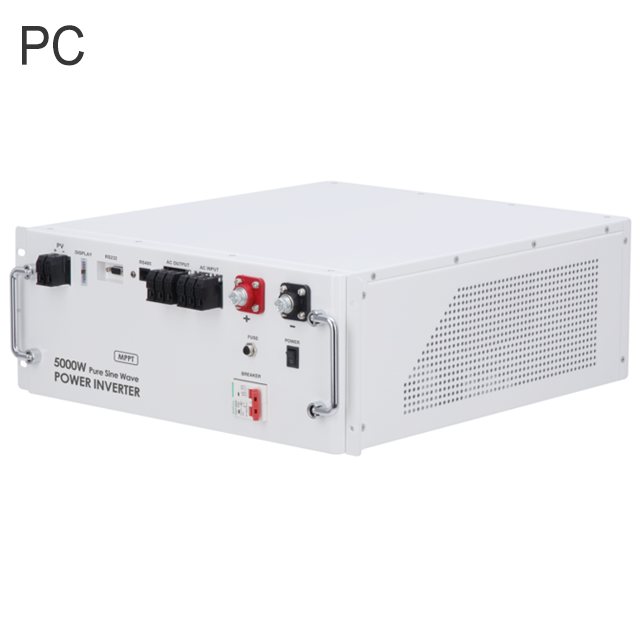
3.2KW 5KW 8KW 11KW PC/PW PV inverter
Key attributes
| Brand | Wone |
| Model NO. | PC/PW PV inverter |
| Mounting type | Wall-mounted |
| Rated Output Rating | 5kW |
| Input Voltage | DC48V |
| Rated PV input power | 5.5kW |
| Series | PC/PW series |
Product descriptions from the supplier
Photovoltaic inverter
Peculiarity:
Dual phase inverter.
IP54 protection grade, support outdoor use.
Backward compatible with traditional lead batteries, colloidal batteries.
PC/PW up to 9 parallel, output power up to 45KW.
The panel integrates a variety of interfaces, supporting a variety of protocols of the host computer and battery pack.
Integrated MPPT, maximize the press of the remaining power of the photovoltaic panel.
Highly integrated, feature-rich, one machine at most.
Can be customized adjustment management battery charging and discharging strategy.
Modular design, easy maintenance.
Technical parameter:


How does MPPT dynamically adjust the input voltage and current?

Online store
On-time delivery rate
Response time
100.0%
≤4h
Company overview
Workplace: 65666m²m²
Total staff: 300+
Highest Annual Export(usD): 50000000
Services
Business Type: Design/Manufacture/Sales
Main Categories: High Voltage Electrical Apparatus/Low Voltage Electrical Apparatus/Wire cable/Instrument meters/New energy/Tester/Production equipment/Generator/Electrical fittings/Integrated Electrical Equipment
Whole life care manager
Whole-life care management services for equipment procurement, use, maintenance, and after-sales, ensuring safe operation of electrical equipment, continuous control, and worry-free electricity consumption.
The equipment supplier has passed platform qualification certification and technical evaluation,
ensuring compliance, professionalism, and reliability from the source.
Related Products
-
8-30kW Three Phase 2 MPPTs Residential Grid-tied Inverters

-
PQstorI Series Energy storage inverter

-
PVI Series Photovoltaic Inverter

-
25-36kW Three Phase 3 MPPTs C&I Grid-tied Inverters

-
0.7-3kW 1 MPPT Single Phase Residential Grid-tied Inverters

-
4-15kW Three Phase 2 MPPTs Residential Grid-tied Inverters

-
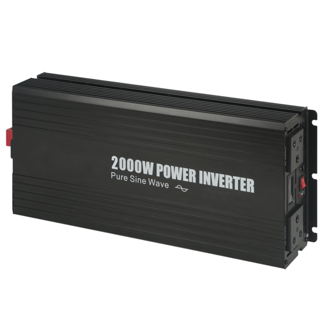
300W 800W 1000W 3000W Power inverter
Related Knowledges
-
 10 Prohibitions for Transformer Installation and Operation!10 Prohibitions for Transformer Installation and Operation! Never install the transformer too far away—avoid placing it in remote mountains or wilderness. Excessive distance not only wastes cables and increases line losses, but also makes management and maintenance difficult. Never choose transformer capacity arbitrarily. Selecting the right capacity is essential. If the capacity is too small, the transformer may be overloaded and easily damaged—overloading beyond 30% should not exceed two hoursJames10/20/2025
 -
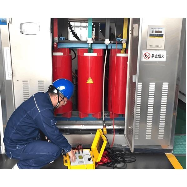 How to Maintain Dry-Type Transformers Safely?Maintenance Procedures for Dry-Type Transformers Put the standby transformer into operation, open the low-voltage side circuit breaker of the transformer to be maintained, remove the control power fuse, and hang a "DO NOT CLOSE" sign on the switch handle. Open the high-voltage side circuit breaker of the transformer under maintenance, close the grounding switch, fully discharge the transformer, lock the high-voltage cabinet, and hang a "DO NOT CLOSE" sign on the switch handle. For dry-type transFelix Spark10/20/2025
 -
 How to Adjust Transformer Tap Positions Correctly?I. Transformer Operating Tap PositionsHow many tap positions a transformer has, that's how many operating tap positions it has?In China, on-load tap-changing transformers usually have 17 taps, while off-load tap-changing transformers generally have 5 taps, though some have 3 or 2.Theoretically, the number of transformer tap positions equals the number of its operating tap positions. When voltage fluctuates during operation, the tap position of an on-load tap-changing transformer can be adjusted,Echo10/20/2025
 -
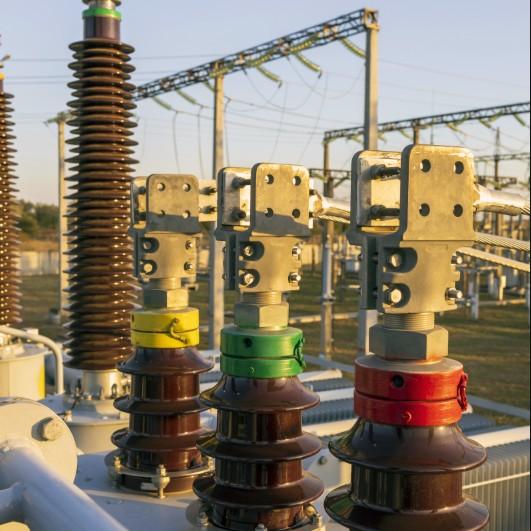 Transformer Bushings: Function, Types & Installation GuideTransformer Bushings: External Insulation and Current-Carrying ComponentsTransformer bushings are the primary external insulation devices mounted on the transformer tank. The leads from the transformer windings must pass through these insulating bushings, which provide insulation between the leads as well as between the leads and the transformer tank, while also serving to mechanically secure the leads.Depending on the voltage level, transformer bushings are available in several types: porcelainJames10/20/2025
 -
 Transformer Life Halved with Every 8°C Increase? Understanding Thermal Aging MechanismsThe length of time a transformer can operate normally under rated voltage and rated load is called the service life of the transformer. Materials used in transformer manufacturing fall into two main categories: metallic materials and insulating materials. Metallic materials generally can withstand relatively high temperatures without damage, but insulating materials will rapidly age and degrade when the temperature exceeds a certain value. Therefore, temperature is one of the main factors affectFelix Spark10/20/2025
 -
 How Hydraulic Transformers Enable Green & Smart Hydraulics1. About the Hydraulic TransformerA hydraulic system typically consists of a hydraulic power source (pump), actuators (hydraulic cylinder or motor), control components, and auxiliary parts. However, one critical component is notably missing—the hydraulic transformer. Hydraulic transmission is often compared to electrical transmission, and hydraulic control systems to electrical control systems, due to their strong similarities and corresponding functional components and parameters. Can we imaginNoah10/20/2025
Haven't found the right supplier yet? Let matching verified suppliers find you.
Get Quotation Now
Send inquiry
Download
Get the IEE Business Application
Use the IEE-Business app to find equipment, obtain solutions, connect with experts, and participate in industry collaboration anytime, anywhere—fully supporting the development of your power projects and business.


