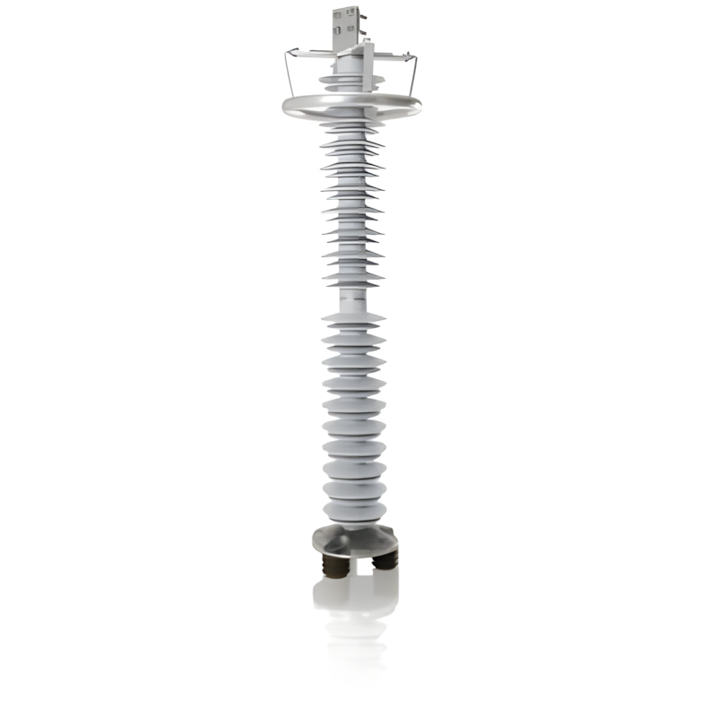
Metal Oxide Surge Arresters for Series Compensation Capacitors

Key attributes
| Brand | ROCKWILL |
| Model NO. | Metal Oxide Surge Arresters for Series Compensation Capacitors |
| Rated voltage | 130kV |
| Rated frequency | 50/60Hz |
| Series | YH43W |
Product descriptions from the supplier
Description
Metal Oxide Surge Arresters for Series Compensation Capacitors are specialized protective devices designed to safeguard series compensation capacitor banks in high-voltage AC transmission systems. These arresters are integrated into series compensation circuits—where capacitors enhance power transfer capacity and voltage stability—to mitigate overvoltages caused by system faults, switching transients, or capacitor energization/de-energization. Equipped with high-performance metal oxide varistors (MOVs), they rapidly divert excessive surge currents away from the capacitors, clamping voltage levels to safe thresholds. By preventing damage to capacitor elements, bushings, and associated hardware, these arresters ensure the reliable operation of series compensation systems, maintaining grid efficiency and reducing the risk of unplanned outages.
Features
Model |
Arrester |
System |
Arrester Continuous Operation |
DC 1mA |
Switching Impulse |
Nominal Impulse |
Steep - Front Impulse |
2ms Square Wave |
Nominal |
Rated Voltage |
Nominal Voltage |
Operating Voltage |
Reference Voltage |
Voltage Residual (Switching Impulse) |
Voltage Residual (Nominal Impulse) |
Current Residual Voltage |
Current - Withstand Capacity |
Creepage Distance |
|
kV |
kV |
kV |
kV |
kV |
kV |
kV |
A |
mm |
|
(RMS Value) |
(RMS Value) |
(RMS Value) |
Not Less Than |
Not Greater Than |
Not Greater Than |
Not Greater Than |
20 Times |
||
(Peak Value |
(Peak Value |
(Peak Value |
(Peak Value |
||||||
YH43W1-130/249W |
130 |
500 |
76.5 |
180 |
249 |
8000 |
4200 |
||
Y43W1-130/249W |
130 |
500 |
76.5 |
180 |
249 |
8000 |
4000 |
||
Y20W1-63/149W |
63 |
46.2 |
500 |
86 |
149 |
8000 |
2400 |

Related Products


Related Knowledges
-
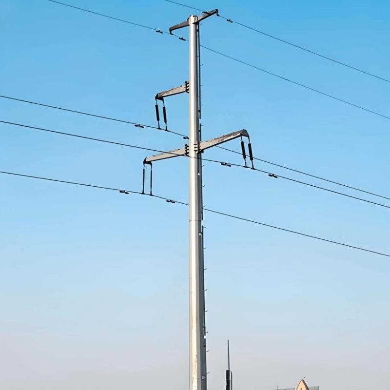 How to Design 10kV Overhead Line PolesThis article combines practical examples to refine the selection logic for 10kV steel tubular poles, discussing clear general rules, design procedures, and specific requirements for use in 10kV overhead line design and construction.Special conditions (such as long spans or heavy ice zones) require additional specialized verifications based on this foundation to ensure safe and reliable tower operation.General Rules for Overhead Transmission Line Tower SelectionThe rational selection of overheadJames10/20/2025
 -
 10kV RMU Common Faults & Solutions GuideApplication Issues and Handling Measures for 10kV Ring Main Units (RMUs)The 10kV ring main unit (RMU) is a common electrical distribution device in urban power distribution networks, primarily used for medium-voltage power supply and distribution. During actual operation, various issues may arise. Below are common problems and corresponding corrective measures.I. Electrical Faults Internal Short Circuit or Poor WiringA short circuit or loose connection inside the RMU can lead to abnormal operatiEcho10/20/2025
 -
 High-Voltage Circuit Breaker Types & Fault GuideHigh-Voltage Circuit Breakers: Classification and Fault DiagnosisHigh-voltage circuit breakers are critical protective devices in power systems. They rapidly interrupt current when a fault occurs, preventing damage to equipment from overloads or short circuits. However, due to long-term operation and other factors, circuit breakers may develop faults that require timely diagnosis and troubleshooting.I. Classification of High-Voltage Circuit Breakers1. By Installation Location: Indoor-type: InstaFelix Spark10/20/2025
 -
 3D Wound-Core Transformer: Future of Power DistributionTechnical Requirements and Development Trends for Distribution Transformers Low losses, especially low no-load losses; highlighting energy-saving performance. Low noise, particularly during no-load operation, to meet environmental protection standards. Fully sealed designto prevent transformer oil from contacting external air, enabling maintenance-free operation. Integrated protection devices within the tank, achieving miniaturization; reducing transformer size for easier on-site installation. CEcho10/20/2025
 -
 10 Prohibitions for Transformer Installation and Operation!10 Prohibitions for Transformer Installation and Operation! Never install the transformer too far away—avoid placing it in remote mountains or wilderness. Excessive distance not only wastes cables and increases line losses, but also makes management and maintenance difficult. Never choose transformer capacity arbitrarily. Selecting the right capacity is essential. If the capacity is too small, the transformer may be overloaded and easily damaged—overloading beyond 30% should not exceed two hoursJames10/20/2025
 -
 How to Maintain Dry-Type Transformers Safely?Maintenance Procedures for Dry-Type Transformers Put the standby transformer into operation, open the low-voltage side circuit breaker of the transformer to be maintained, remove the control power fuse, and hang a "DO NOT CLOSE" sign on the switch handle. Open the high-voltage side circuit breaker of the transformer under maintenance, close the grounding switch, fully discharge the transformer, lock the high-voltage cabinet, and hang a "DO NOT CLOSE" sign on the switch handle. For dry-type transFelix Spark10/20/2025
Related Solutions
-
 Intelligent Operation Solution for 12kV Vacuum Circuit Breakers: Integrating Real-time Monitoring & Lifetime OptimizationⅠ. Equipment Operation & MaintenanceIntelligent Monitoring System IntegrationMulti-parameter Real-time Monitoring: Embedded sensors (temperature, displacement, Hall effect current sensors) track contact temperature rise, mechanical characteristics (opening/closing speed, overtravel), coil current, and partial discharge signals. Data undergoes preprocessing via edge computing prior to cloud upload.Lifetime Prediction Model: Dynamically evaluates remaining lifespan using electrical wear dataRockwill06/10/2025
 -
 SF6 Circuit Breaker Solutions for Outdoor Installation (Anti-Pollution & Seismic Resistance)I.Core Challenges in Outdoor InstallationIn high-voltage transmission and distribution systems, SF6 circuit breakers are exposed to complex outdoor environments for extended periods, facing the following critical issues:Pollution & Insulation DegradationDust, salt fog, and industrial pollutants in outdoor environments easily adhere to equipment surfaces. In coastal or industrial areas, pollution levels may reach Class IV, resulting in insufficient creepage distance and triggering flashoRockwill05/12/2025
 -
 12kV Indoor Vacuum Circuit Breaker Southeast Asia Solution: Anti-Corrosion Compact Design12kV Indoor Vacuum Circuit Breaker Southeast Asia Solution: Anti-Corrosion Compact DesignⅠ. Executive SummarySoutheast Asia faces rapidly growing electricity demand alongside environmental challenges including high temperatures, humidity, salt spray corrosion, and grid instability. This solution recommends Solid Insulated Pole-Mounted Vacuum Circuit Breakers (VCB) featuring high reliability, compact design, and smart monitoring. Tailored for tropical climates and industrial scenarios, itRockwill06/10/2025


