3D Wound-Core Transformer: Future of Power Distribution

Technical Requirements and Development Trends for Distribution Transformers
Low losses, especially low no-load losses; highlighting energy-saving performance.
Low noise, particularly during no-load operation, to meet environmental protection standards.
Fully sealed design to prevent transformer oil from contacting external air, enabling maintenance-free operation.
Integrated protection devices within the tank, achieving miniaturization; reducing transformer size for easier on-site installation.
Capable of loop-network power supply with multiple low-voltage output circuits.
No exposed live parts, ensuring safe operation.
Compact size and light weight; reliable operation with convenient maintenance and upgrades.
Excellent fire resistance, earthquake resistance, and disaster prevention performance, expanding application range.
Strong overload capacity, meeting emergency power demands during failures in other equipment.
Further reduction in production and sales costs to enhance affordability and market acceptance.
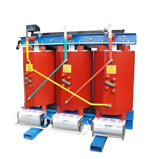
Based on the above analysis, three-dimensional (3D) wound-core distribution transformers represent an ideal development direction. Currently, energy-efficient models such as the S13 and SH15 amorphous alloy distribution transformers best meet domestic market demands. For installations requiring fire safety, dry-type distribution transformers with epoxy resin casting are recommended.
Key Considerations in the Use of Distribution Transformers
Based on the above conclusions and practical experience, the following operational guidelines for distribution transformers can be clearly understood. These are presented as recommendations without detailed technical justification—further discussion can be conducted in specialized topics.
When selecting a distribution transformer, consider not only its performance but also appropriate capacity selection based on actual load size to ensure high load utilization.
If the capacity is too large, the initial investment and purchase cost increase, and no-load losses are higher during operation.
If the capacity is too small, it may fail to meet power demand, and load losses tend to be excessively high.
Determine the number of transformers reasonably, considering both safety and economy:
For facilities with large amounts of critical (Class I) loads, or even Class II loads requiring high security, consider installing multiple units (e.g., one large and one small) when load fluctuations are significant and long intervals occur.
For high reliability requirements, provide a standby transformer (subject to space and other constraints).
If lighting and power share one transformer and lighting quality or lamp life is severely affected, a dedicated lighting transformer should be installed.
Economic operation of transformers is a complex systemic issue.
Maximum efficiency occurs when no-load losses equal load losses—this is difficult to achieve in practice.
Consider the economic operation curve and optimal economic operation curve. Generally, transformers operate most efficiently and economically at 45%–75% load rate.
However, this varies by transformer type and capacity and should be evaluated individually. Refer to Professor Hu Jingsheng’s book Economic Operation of Transformers for detailed calculations.
Reactive power compensation for distribution transformers must be properly managed—neither over-compensation nor under-compensation.
Improves power factor
Reduces line losses
Enhances operating voltage
The actual power factor should generally reach 90% or higher.
The losses introduced by capacitors themselves must be considered.
Proper compensation brings significant energy-saving benefits:
Compensation methods include: group compensation, centralized compensation, and local (at-load) compensation.
When selecting and operating transformers, pay attention to the secondary output voltage.
Consider the system voltage conditions, select the appropriate turns ratio, and correctly set the tap changer position to meet customers' requirements for voltage quality.
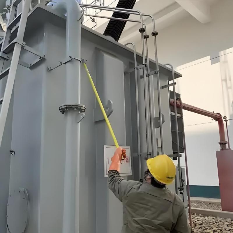
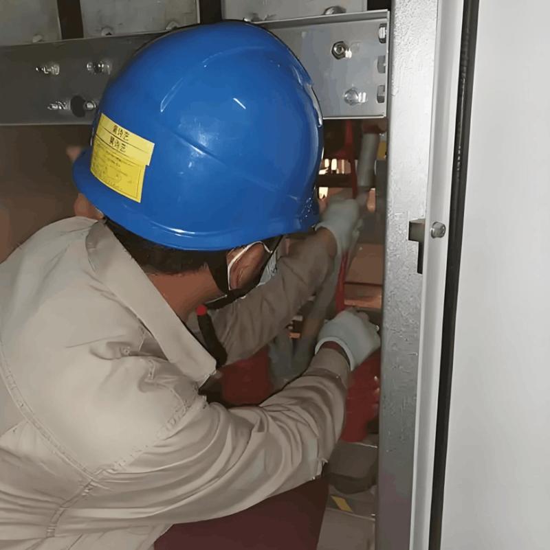
Strengthen operation and maintenance of distribution transformers.
While current systems often adopt a "condition-based maintenance" approach (repair only when defects occur), scientific inspection procedures are essential.
Key points include: avoiding long-term overload operation, maintaining proper oil level, normal temperature indication, and acceptable noise levels. Regulations already provide detailed guidance.
Other aspects such as safety, civilized production, service life, investment return, and installation location selection also impact transformer use. These topics are not discussed in detail here.