• High - voltage pneumatic load break switch
High - voltage pneumatic load break switch
discuss personally
Model
FKN-12/630
Basic info
Brand ROCKWILL
Model NO. High - voltage pneumatic load break switch
Rated voltage 12kV
Rated normal current 630A
Rated frequency 50/60Hz
Series FKN
Product Detail

Product Overview

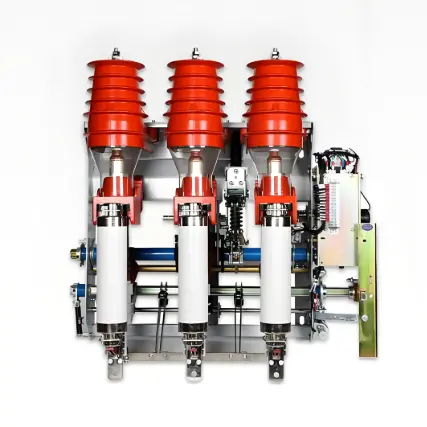
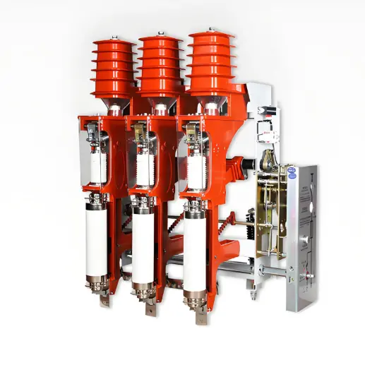
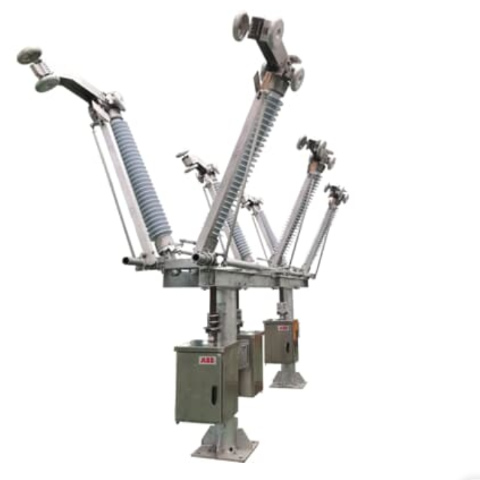
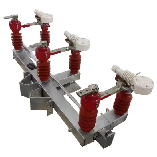
The s high - voltage pneumatic load break switches and their combined electrical appliances are indoor high - voltage switchgear for AC 12kV, 50Hz. This load break switch features high specific technical parameters and reliable action. The basic form of the operating mechanism is manual spring - energy - storage type, and it can also be equipped with an electromagnetic spring operating mechanism. Based on the pneumatic arc - extinguishing principle, it can interrupt multiple times without replacing the arc - extinguishing tube.

The high - voltage load break switch can close, carry and open load currents under normal circuit conditions, and has the capability to close short - circuit currents and open short - circuit currents within a specified short time.

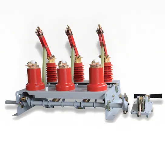
The  load break switches can be equipped with earthing switches. The earthing switch has the same short - circuit making capacity as the load break switch, as well as the dynamic and thermal stability capability, and has a strict mechanical interlock with the load break switch, ensuring that misoperation is impossible in terms of structure.


Key Features

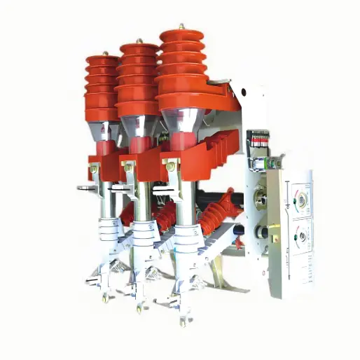
  • When the FKN12 - 12 load break switch is equipped with a high - voltage current - limiting fuse (with a striker) to form a load break switch - fuse combination, it serves as overload and short - circuit protection for loads (such as power transformers). When one or more phases of the fuse blow, the three phases of the load break switch automatically open.

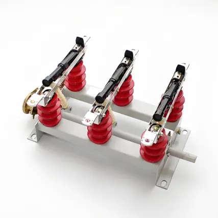
  • The high - voltage load break switch is suitable for installation in ring - main unit switch cabinets and other types of switch cabinets for receiving and distributing electrical energy.

Technical Parameters

Serial No.

Name

Unit

Value

1

Rated Voltage

KV

12

2

Rated Frequency

Hz

50

3

Rated Current

A

630

4

Maximum Rated Current of Fuse

A

100

5

Rated Active Load Breaking Current, Rated Closed - loop Breaking Current

A

630

6

Rated Short - time Withstand Current (2S)

KA

20

7

Rated Short - circuit Making Current, Rated Peak Withstand Current

KA

50

8

1min Power Frequency Withstand Voltage, Phase - to - phase and to - ground / Break

KV

42/48

9

Lightning Impulse Withstand Voltage (Peak Value), Phase - to - phase and to - ground / Break

KV

75/85

10

Rated Cable Charging Breaking Current

A

10

11

Rated Breaking of No - load Transformer

KVA

1250

12

Mechanical Life

Times

2000

13

Rated Breaking Transfer Current

A

1150

14

Rated Short - circuit Breaking Current of Fuse

KA

31.5

Main Mechanical Characteristics of Load Break Switch

Serial No.

Name

Unit

Value

Remarks

1

Phase - to - phase Center Distance

mm

210 ± 3


2

Total Stroke of Conductive Rod

mm

215 ± 5

3

Distance Between Moving and Static Arc at Opening Position

mm

>160

4

Over - stroke of Electrical Contact of Moving Contact Rod

mm

42 ± 3

5

Just - Closing Speed

m/s

3.8 <sup>+0.7</sup><sub>-0.2</sub>

6

Just - Opening Speed

m/s

>2.7

7

Three - phase Closing Asynchronism

ms

>10

Contact between moving contact rod and contact fingers

8

Three - phase Opening Asynchronism

ms

>5

Separation between moving contact rod and contact fingers

Operating Environmental Conditions

  • Altitude: Not exceeding 1000m.

  • Ambient Temperature: Maximum +40&deg;C, Minimum -10&deg;C.

  • Relative Humidity: Daily average not exceeding 95%, Monthly average not exceeding 90%.

  • Seismic Intensity: Less than 8 degrees.

Know your supplier
ROCKWILL
Rockwill Electric Group Global Manufacturer of High voltage and medium-voltage power equipment and smart grid solutions. Headquartered in Wenzhou, China. Serving 100+ countries with quality, innovation, and trust. What We Offer: • HV-MV switchgear (VCB, SF₆ circuit breakers, RMU, GIS) • Distribution transformers and substations • Smart grid and monitoring systems • Solar, wind, EV charging, and energy storage solutions • EPC turnkey power projects Certified: ISO 9001 / ISO 14001 / ISO 45001
Main Categories
High voltage
Business Type
Design/Manufacture/Sales
Highest Annual Export (USD)
$150,000,000
Professional Experience
16 years
Workplace
108000m²m²
占位
占位
Related Products
Related Knowledges
What are the common faults that occur when low-voltage current transformers are combined with other power equipment?
Low-voltage current transformers, as indispensable measurement and protection devices in power systems, often encounter various faults when used in combination with other power equipment due to environmental factors, equipment linkage issues, and improper installation and maintenance. These faults not only affect the normal operation of power equipment but may also endanger personal safety. Therefore, it is necessary to gain an in-depth understanding of fault types, judgment methods, and prevent
Felix Spark
07/17/2025
What are the monitoring methods and future development trends of low-voltage voltage transformers?
With the continuous advancement of smart grid technology, intelligent monitoring systems are playing an increasingly important role in preventing and addressing faults in voltage transformers. These modern intelligent monitoring systems can collect key parameters from voltage transformers in real time—such as partial discharge levels, temperature, and oil quality—and use data analysis algorithms to assess the health status of the equipment, enabling early fault warnings and precise l
Echo
07/16/2025
What are the common faults of low-voltage voltage transformers?
1. Open - Circuit Fault on the Secondary SideOpen - circuit in the secondary side is a typical fault of low - voltage voltage transformers, showing abnormal voltmeter readings (zero/fluctuation), faulty power meters, buzzing noises, and core overheating. When open - circuited, the secondary voltage spikes (no secondary current to balance the primary EMF), causing core saturation, flux distortion, and potential overheating/damage.Causes include loose terminals, poor contact, or human error. In lo
Oliver Watts
07/16/2025
A Quick Verification Method for Low-Voltage Current Transformers
1. Selection of Low - Voltage Current Transformer ConfigurationThere are many factors leading to wrong selection of low - voltage current transformers in civil construction projects. For example, common factors include design problems: the calculated coefficient designed for the load of electrical equipment is relatively large, or the transformation ratio of the current transformer is selected incorrectly. Such a series of reasons will affect the use of electrical equipment. Therefore, in the co
James
07/16/2025
A Quick Verification Method for Low-Voltage Current Transformers
To ensure safe operation of the power system, power equipment operation must be monitored/measured. General devices can’t connect to primary high - voltage equipment directly; instead, large primary currents are scaled down for current transformation, electrical isolation, and use by measurement/protection devices. For AC large - current measurement, conversion to a unified current eases secondary instrument use.Current transformers split into measurement - and protection - type, with accu
Oliver Watts
07/16/2025
Research on Low - Voltage Anti - DC Current Transformer and Detection Device
1. Overview of Components and IssuesTA (low-voltage current transformer) and electric energy meters are key components of low-voltage electric energy metering. The load current of such meters is no less than 60A. Electric energy meters vary in type, model, and anti-DC performance, and are connected in series in the metering device. Due to the lack of anti-DC capability, they suffer from metering errors under DC component loads, usually caused by non-linear loads. With the increasing use of DC or
Dyson
07/16/2025
×
Inquiry
Download
IEE-Business is dedicated to serving the personnel in the global power industry.
Join IEE-Business, not only can you discover power equipment and power knowledge, but also canhnd like - minded friends!